October 11,
Not much has gotten done over the last two weeks. I've been at the hospital looking after my dad. Hopefully he will be home in the next few days.
I did manage to get a little work in over the weekend.
 |
Looks like the right angle drill is the perfect size for cutting the 1 5/8" (4.13 cm) limber holes between floor timbers. 5" thick white oak is not easily drilled though. It will be a bit of work. I'm using that diameter because I have a source of copper tubing that, if I choose, I can hammer into the limber holes to make them more robust. I also started drilling limber holes in the longitudinals between floor timbers. I'm only drilling 1/2" (1.25 cm) holes for these.
|
Cutting the "H" beam with an inexpensive die grinder with a cut-off blade. Be careful when cutting something that large. Keep your face out of inline with the blade. Those blades can shatter and send shrapnel right through your head. If it wasn't for COVID 19, I'd wear a face shield but they are in high demand right now. At the very end my disc jammed and sent fragments into the wall behind me. If my head was in the way, I don't think it would have slowed those fragments down much. Scared the hell out of me. I also jammed the grinder so bad it might not be worth repairing. I was so close to being done with the cut that I was able to finish it off with a few minutes of sawzall action.
I also made a mockup of the "H" beam that will be the mast step girder and support for half the ballast keel. I used the mockup to plan a sequence of actions that will maximize the accuracy of the installation. Later, the ballast keel will be lifted to the hull and those 1" (2.5 cm) threaded rods had better fit perfectly.
October 26,
I've identified several holes that need to be drilled into the "H" beam prior to the galvanizing process.
- 1" holes for the ballast keel
- 1/2" holes for lag bolts that will hold the "H" beam in place forward of the keel bolts
- 3/16" holes for mounting wood to the side in order to mount sole framing
- 1/4" holes along the webbing to mount the gray water, black water, and fresh water lines
- 1/4" holes port and starboard to electrically connect the beam to the bonding rods
The bonding rods that run the length of the boat on both the starboard and port side will be connected to the mast step girder via copper cable. I'm going to use copper ring terminals that I'm going to tin myself in order to isolate the copper from the zinc of the galvanizing. I'm also planning to use a lead sheet barrier between the mast foot and the zinc. I don't want to loose the zinc on the beam to any unnecessary galvanic interactions.
October 28
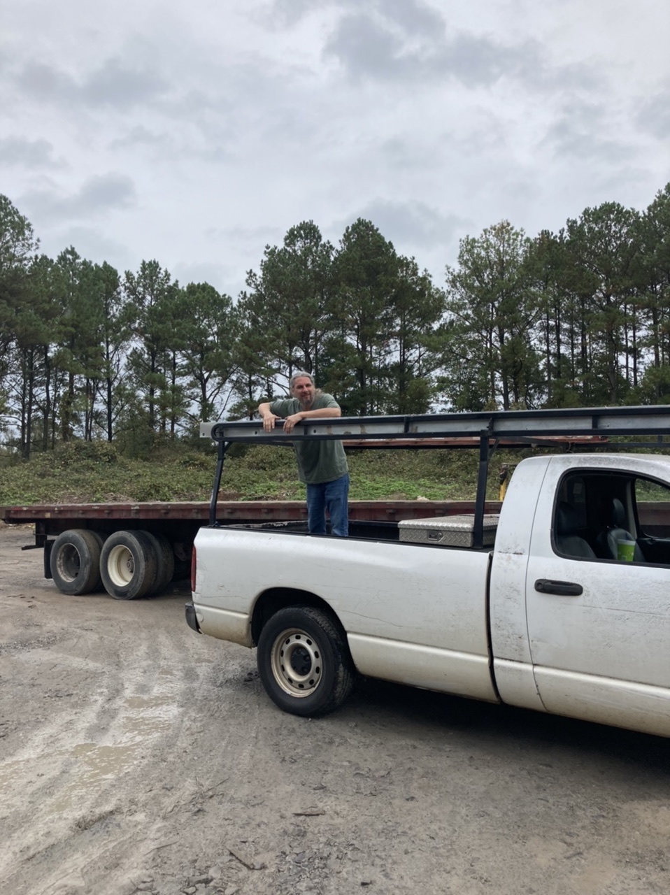
Took a trip down to Hansville Alabama (1 hr 15 min.) to visit Kennedy Galvanizing. They were able to galvanize the mast step girder in the same day for a very reasonable price. They loaded it up on the truck with it still pretty warm. Now we got to get that thing in the boat.
 |
About to off load that beam.
|
 |
| Laura taking a selfie in front of the galvanizing tanks. |
 |
| See ya later steel beam. |
 |
A few hours later it is sitting outside waiting for us.
|
 |
| With my name on it. |
 |
| Yep, still very warm. |

 |
| Securing it for the ride back to Huntsville. |
 |
| Someone else's parts. |
 |
| Setting up rigging to get the beam in the boat. The beam weighs 250 pounds (113 kg). I have one chain hoist over head and one horizontal to control the lateral movement. I had just enough swing so there was no need for muscle. |
 |
The galvanizing work is scrutinized by Fig.
|
 |
| Preparing the rigging. This chain hoist will let the beam swing onto the boat. |
 |
| Coming up the side. I have some old lumber protecting the side of the boat. |
 |
| Almost there. |
 |
| A big smile because the hard part is over. |
 |
| It is in! |
 |
| My wife Laura. She is ready on the chain hoist. Actually, I could not do this without her. |
 |
| In the boat after not that much difficulty. You can see that it will eventually be moved to those notches in the bulkhead. |
 |
| And this is where it lays. |
 |
| Drilling those 1-5/8" holes are a real pain. With Laura applying leverage, all I have to do is guide the drill. Easy as can be with two. Hard as hell with only one. |
 |
| Halloween beer witch. |
 |
| I used some 3/8" exterior grade bead board plywood here for the ceiling because frankly it's in the back of a locker and will never be seen. This wood is left over from a home restoration and was previously primed with exterior grade primer. Unfortunately, the primer was rolled on and I hate roll texture so I sanded it smooth with a belt sander. Actually, the surface of this plywood is not that great so I'd have to sand it anyway. It will look good painted. |
On the far side is that locker shown above and on the near side is the lavatory. Again, for the lavatory, there will be none of this plywood showing since it will actually be the back of closets above and below the lavatory. I'm going to pull all of this back out and prime both sides before final installation.
 |
After removal, priming all sides, and reinstalling.
|
I used roofing tar paper to make patterns for the plywood. You can tell the rather complicated shape this piece has.
 |
Preparing to install the ceiling. I've added 5/16" vertical spacers so that when I plank the ceiling, I will have good air flow from the bilge up to the gunwales.
|