April 5,
I have not posted in awhile but work continues. I've had other priorities lately but I'm getting back into the swing of things. I have decided to concentrate my effort on getting the middle of the boat finished on the inside. This means I have to figure out how I am going to install the sole. As you can see in the photos below, I have a system. Two things are critical: I wanted the sole to look good but have plenty of access to the bilge. The table saw was set up to remove the tongue on select pieces while the router table was set up to add a groove (for the tongue) where there was a tongue. This way, I can turn the tongue and groove flooring around at will making a square hatch hole with the tongues all facing in. The hatch had all the grooves facing out and the bottom of the groove removed so the hatch fits neatly in the hole supported by the tongues. I really need a diagram for that.
 |
| Four access hatches to the bilge with one hatch in place. I can access the keel bolts and all the plumbing. |
 |
| All four hatches temporarily in place to check fit. I'll remove them and glue them into one piece on a jig to keep them square. I'll use West System epoxy as usual. |
I have been thinking a lot about the sliding door that acts as an entrance point for the cabin above. I looked into marine grade rails and hardware but they were very expensive and did not look very durable so I decided to build my own. My first thought was to build everything out of wood that I already have. The upper rail where the door would hang just seemed too clunky (design not shown). I decided that a metal square tube with a slot cut down one face would be better. I sourced some 6061 T6 aluminum from Metal Supermarkets (metalsupermarkets.com). They had what I needed for less than $70. All I had to do was machine the slots.
 |
| The sliding door is on the far left hanging from a 1.5"x 0.75" aluminum square tube with a 3/4" slot cut down on face. The door and wall are 1/4" and 3/8" panels respectively. The rail and styles are similar to the cabinets with the exception that the ones used on the wall are 1" thick. The door rides on two 3/4"x 1.4" HDPE blocks that are screwed into the top rail of the door. Additional HDPE blocks (light gray) are shown elsewhere to stabilize the door. |
 |
| The door is shown on the bottom left from a top view. The rail (1/5"x3/4" aluminum) with two slots cut out is shown above but artificially rotated and displaced upwards to show the channels. The light gray blocks will ride inside the channel. The area labeled 'opening' is the actual door opening. |
 |
| Close up of HDPE slide block. You should also notice that the slot is offset from center in order to minimize the space between the sliding door and wall. |
April 9,
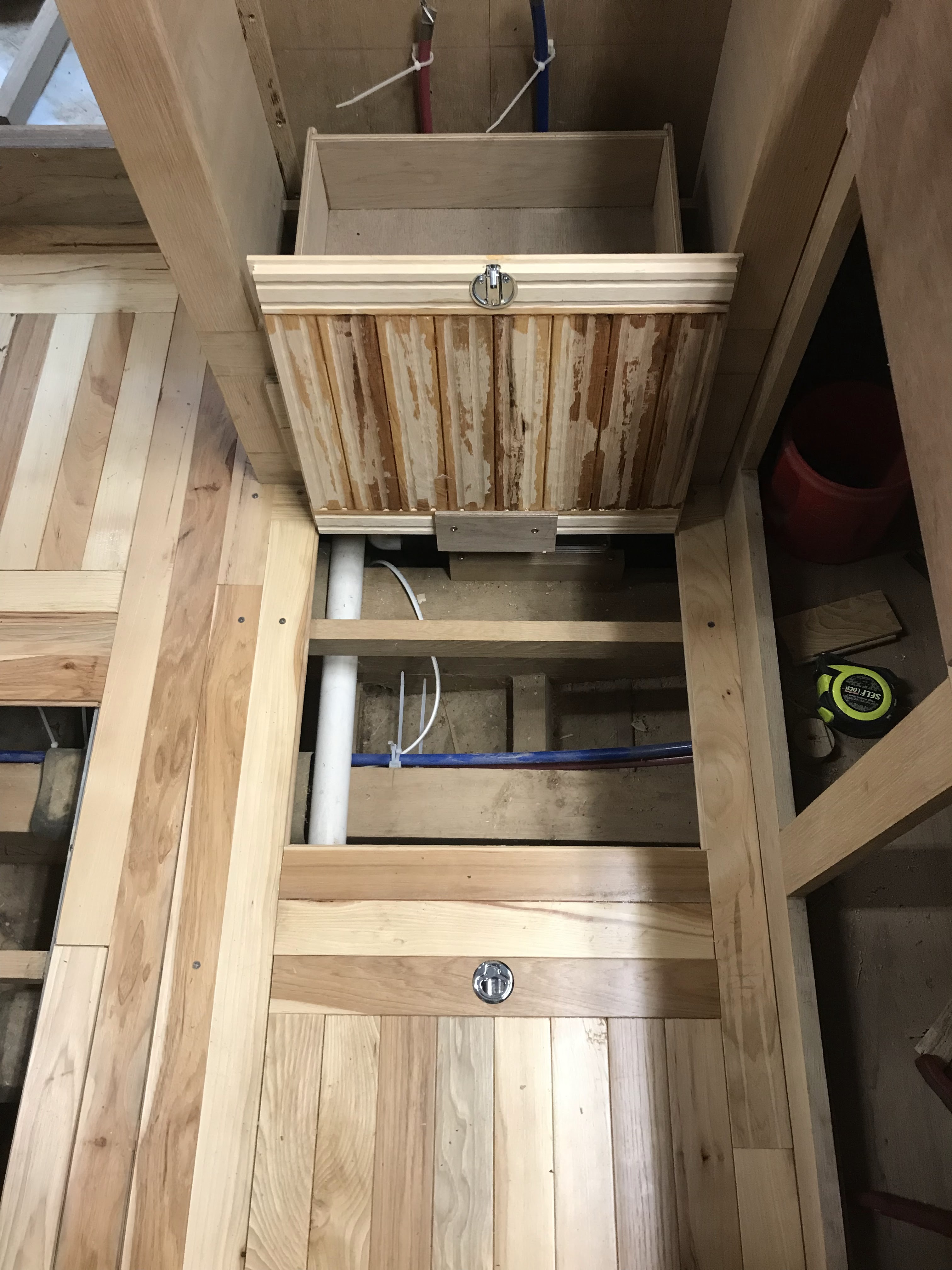
Back to the sole. I have avoided installing the sole because a) I knew it would be a pain in the ass and b) I wanted to have access to everything in the bilge before the sole is installed. I decided that I'd have more access to the bilge by way of access hatches that act as decorative mosaics and just get it done. One of the inspirations was using the router and table saw to make double sided (groove on both sides instead of tongue and groove) boards so that I can have a tongue exposed completely surrounding the hatch that acts as a lip the hatch can sit securely on. The hatch has a groove around their perimeters with the bottom part of the groove cut away so that it sits on the tongues of the hatch opening.

 |
| Three of the hatches are glued together and placed where they are suppose to be. Wooden mallet is on one, drill is on another, and rusty framing square is on the third. The fourth is being glued up. Near the entrance at the upper part of the photo, I have started a new opening for a hatch that will be in front of the shower. That one will have access to the plumbing run and one keel bolt. |
 |
The hatch in front of the shower laid in place. I glued it up yesterday and it is still in its jig. The next access hatch will be for the through-hull seacock for the head and another keel bolt.
|
April, 21.
April 28,
A bit of work today fitting the seacocks to the hull. I also worked a bit on the ceiling. That is the tongue and groove wall boards. I have to finish two areas (actually closets) before I complete the sole for the forward part of the boat. This is probably the most complicated part of the sole due to the number of access hatches. The aft part where the settees are and the galley will be much simpler since there will only be a few access panels because tankage takes up so much of that space below the sole.

|
| I have added a few layers of epoxy to the glass I laid to support the through hull fitting for both water inlets to the heads. After sanding flat, I placed the through hull fitting with base plate where I wanted it and marked the outline with pencil. Next, I made a paper pattern of the base to locate the center and used that pattern to mark where I will drill the 1" hole. The entire seacock and flange is temporarily installed to locate the flange bolt holes which are subsequently drilled. Both the 1" hole and bolt holes will be coated in epoxy in case any water should seep through. The bolts and nuts are silicon bronze and will be sealed with slightly thickened epoxy. The idea is to wet out the holes with un-thickened epoxy and let them cure for a few hours and then use slightly thickened epoxy to seal the bolts and the outside part of the seacock. Replacing them will require the bolts and exterior parts to be ground off and re-drilled. These are serviceable and I don't expect to every replace them but you never know. |