Monday, December 31, 2012

The Transom

The Transom

The transom is one of the most important pieces of a boat.  Traditionally it is the weakest part and generally targeted during naval battles (this goes back to the very first naval battles that used rams as the armament and continued through the development of the cannon, on the other hand it probably didn't matter where a modern torpedo hit you).  A failure in the transom has caused many a boat to go down.  the transom keeps the boat true.  The inherent sharp transition at the keel at the lack of timbers created the weakness.  The canoe removed this weakness by making the boat have essentially two bows front and back.  This design was utilized in large vessels as well as the common river variety that we are familiar.  In fact, you see many modern sailboats with this double ended design today.  Modern boat building techniques have largely reduced the liability of the transom to negligible levels. Nevertheless, I wanted to take particular care in constructing this part of the boat.  I'm not actually sure that I took extra care in its construction because I've been taking pretty damn extra care in the construction of the entire vessel but I will say that I was extra aware during this phase especially with all the difficulty this part caused me.  There are no patterns for the transom in the blue prints for this boat.  The plans call for taking the shape of the transom from the actual work after a few longitudinal battens are installed.  Really!  I'm looking at the stern of the boat and seeing the longitudinal battens forming nothing resembling the transom.  The port side of the boat in no way resembles the starboard side.  The reason is that no two pieces of wood will bend around the hull the same.  They all have slightly different internal tensions and, even though they might all start out straight, once you start bending them they will act different.  Here is where I deviate from the written instructions of the plans (this won't happen very often).  I decided to take the shape of the transom directly from the table of offsets.  Of course only the projection onto the flat sheet is provided by the offset tables but I'm pretty good at projections and undoing them.  Fifteen years working with sheet metal and creating finials and other decorative items out of flat stock well prepared me for this task.  The table of offsets show a beautiful wineglass shaped transom.  I spent some time transferring the lines to a pattern and voila' I had the transom shape I wanted.
Half the transom pattern shown upside down.  Never make a full sized pattern of a symmetrical piece.  You will never be able to get it perfectly symmetrical and these asymmetries will be magnified when you transfer the shape to the working piece.  Instead make half patterns and flip it to draw the second half.  This will ensure that the final piece is symmetric which is usually more important than getting the shape perfect. 

  I butt glued some plywood together and cut the first layer of the transom out (I had to include a little extra material around the edges because these edges would later be beveled to the shape of the hull).  The next and much more difficult part was placing the transom at the right angle and orientation at the rear of the boat.  For this, I built a jig (I'm a big fan of jigs).  Okay, so now the transom is on the jig and in position.  I have longitudinal battens rough cut to length on both sides.  I still have to install the frame on the transom (the transom frame will be a double lamination of 5/4" oak 6" wide).  I still do not know how to install the frames and notch them for the longitudinal battens without cutting into the transom itself (which according to the plans is a no no).  I decide to install a few longitudinal battens on the transom.  This is very rewarding because now I'm starting to see how the wine glass transom completes the beautiful lines of this boat.  After 3 or 4 longitudinal battens are installed on each side of the boat I decide it's time to tackle the frames.  
The installed transom with the frame transitioning from the inside of the battens to the edge of the transom.  The top of the picture shows the last of the frame pieces being glued in place with West System epoxy.  I used the West epoxy instead of the resorcinol glue because resorcinol glue has no filling capability.  This was a difficult glue-in procedure and I was unable to prevent small gaps in the work.  West System epoxy will remain at full strength with gaps (actually strong clamping pressure is discouraged with epoxy) while the resorcinol glue will loose most of its strength if not properly clamped.  I was able to make two notches in the frames before they were installed thus eliminating the need to notch the transom.  See the top two notches.  Actually I wasn't real happy with these notches which helped validate my decision to notch the first layer of the transom.  I felt with the my use of epoxy, which was not a design requirement, I would compensate for any weakness imparted onto the transom.
 Building the curved frames with complex notches cut in them using measurements only was a challenge.  I threw more than one piece of white oak into the kindling pile.  Worse, once I had a piece I liked it proved impossible to actually put into position.  There was no way to fit the finished piece onto the transom (I even tried a hammer).  This was a three dimensional puzzle that I could not crack.

My First attempt at making the frames around the longitudinal battens.  No matter how you twist or bang on this piece it will not fit due to the complex angles that the battens have as they meet the transom.  I made a pattern out of paper that fits perfectly but paper is two dimensional and bends easier than wood.  Time for plan 'B'.  I make this photo after I had finished the plan 'B' installation so you can see the finished solution behind this frame fragment.
Worse, the longitudinal battens were permanently installed so removing them was not an option.  Time for plan B (it's good to have a plan B).  I decided to move the frames to the inside of where the battens would be placed and then have them transition to their proper place once passed the installed battens.  I would later use dead wood between the battens to fill in the frames.  This would retain or even improve on the structural integrity of the transom while providing a way to attach the hull laminations.  For the battens not yet installed, I would notch the frames and the transom in contradiction to the plans.  I was pretty sure that the use of epoxy would offset any issues caused by cutting into the first layer of the transom (I must say that epoxy is not a miracle material and is no substitute for good craftsmanship.  I've seen epoxy cover a multitude of sins and just wonder at how those sins will surface later down the road.  Although it has saved my ass once or twice).  Luckily, only one layer of the transom was installed so the second layer would not be notched.  I have a thought to add a third layer to the transom so that there will be two un-notched layers on the transom.  To date, I have not decided.  I have figured out how to avoid this whole issue in the future.  The transom should have been made out of temporary material with the permanent frame attached.  The temporary transom and frame are then notched for the battens with the battens only being attached to the frames.  Once the battens are installed, the temporary transom is removed, the battens are cut flush to the frame and then both layers of the permanent transom is installed.  This sequence is easier than what I went through and conforms more closely to what the architect had in mind.  Lessons learned and passed on to you.

This image shows the frame transitioning form the inside to the outside of the battens.
After the dead wood is filled in between the battens.  A few more battens have been installed in this photo.  The hull shape is starting to look sweet.
A close up of the inside of the transom showing the frame transition.  This photo also shows the filler pieces in between the battens.  The work looks pretty messy because I wanted to make sure the pieces were well epoxied.  A bit of sanding will clean this right up.

Sunday, December 30, 2012

Floor Timbers

Floor Timbers

The floor timbers are large oak timbers that sit in the bottom of the hull.  Every bulkhead has one bolted to it plus there are several that float between bulkheads mid ship.  The ones that float are held in place by the longitudinal battens and are bolted to the keel.  They are called floor timbers because the sole is typically attached to them but they exist to hold the 12,400 pound ballast keel to the bottom of the boat. This ballast keel acts as a counterpoint to the force the wind places on the sails.  Extending four of five feet from the bottom of the boat the keel and the hull need to be rigid.  Long stainless steel bolts will pass through the ballast keel and into these floor timbers.  Where the ballast keel is located there is a floor timber every 12" or so.  The floor timbers that support the ballast keel are 4" thick with some roughly 14" wide.  The others that simply mount to the bulkheads are 3" thick and no more than 10" wide.  Their lengths vary from 6 to 12 feet.  Naturally I had to get these timbers custom cut which means green lumber.  Luckily, I ordered the lumber (from Davie Ashley Sawmill in Elora, Tn) in the fall which means that the trees had lost their sap when cut.  This speeds up the seasoning time for the lumber.  Nevertheless, I would have to wait a year before I could make the floor boards.  I didn't wait a year, I waited about six months.  I bought a moisture meter which was suppose to tell me when the wood was dry enough to work.  What it told me was when the outer half inch was dry enough to work.  Making a long story short, before bonding the timbers permanently to the bulkheads I took them back down and re-planed them flat so that they would mate flush to the bulkheads.  

Leaving Davie Ashley Sawmill in Elora Tennessee.  Thats a 16 foot trailer.  
Some of these timbers weighed several hundred pounds.  Remember at this point they are still green.  We had to get creative in unloading these.  We could not pick them up or slide them.  I used 1" iron pipe to roll them out Egyptian style.  Al's having a little fun while riding the wood off the trailer.  
After the timbers were mostly seasoned, I made patterns from the high side of the bulkheads.  This meant that I marked where the bulkhead top would be on what would be the widest side of the bulkhead.  Since all the bulkheads would eventually be tapered to follow the curve of the hull, there would always be one side a little longer than the other.  I needed to err on the side of wide when making these floor timbers.  I ended up with a pattern for each bulkhead.  When cutting out the floating floor timbers, I would use the largest bulkhead pattern in that area.  Few of the timbers were narrow enough to fit through the table top planer (12").  I planed the ones I could and precut the ones I thought would squeeze through after cutting to size.  The very wide ones I smoothed down with the hand power planer.  This was very time consuming.  I actually finished them with a hand planer to knock off the high spots.  They were all temporarily put in place and marked for the keel notches.  They were reinstalled and the keel notches were tweaked with hand saw and chisel.
Floor timbers with keel notches loosely where they will later be installed.  The ones grouped together are the floating floor timbers.
All the floating floor timbers needed to be shaped to the hull before the battens were installed.  There was no way I was going to be able to keep the hull fair while installing the battens any other way.  I came up with a clever scheme for making this happen.  I screwed 1" blocks of wood to a long batten with the same spacing as the bulkheads.  I then clamped the batten to the bottom of the bulkheads with the one inch blocks between the bulkheads and the batten.  If the floor timbers got in the way, I rough cut them down so that they were the correct size within that one inch margin.  The batten made a smooth spline that simulated the hull shape except one inch below the actual hull (or above the hull line depending on perspective).  I was then able to measure down one inch and mark both sides of the floor timber (actually I used a 1" marking block).   I repeated this procedure from one side of the floor timber to the other marking every few inches.  I then nailed brads where the marks were and bent a thin batten over the nails clamping one side to the closes longitudinal batten.  The thin batten created a fair line between the nails/marks.  This was the hull line for that side of the floor timber.  Once repeated on the other side of the floor timber, I used the hand held power planer to remove material down to the lines.
The batten with 1" block spacers that was used to shape the floor timbers.  Each 1" block would sit on top (bottom of the boat) of a bulkhead.
The floor timbers temporarily in place with one of four layers  of the keel laid in the notch.

Another view of the floor boards.  These have been shaped to the contour of the hull using the method described above.
First floor timber bolted and epoxied in place.  This small floor timber only merited two 6" X 3/8" stainless steel bolts.  

Second floor timber bolted and epoxied in place.  Most floor timber merit four 6" X 3/8" stainless steel bolts. 

Moving forward

Moving forward: The Last Bulkhead Under the Stem.

It was time to place the last bulkhead.  This one goes under the stem where the notch is located.  Forward of this bulkhead will later become the chain locker and storage.  To the rear of the bulkhead, will be the vee berth or forward cabin bed.  It's shaped like an inverted "V" to conform to the tapering hull line.  placing this bulkhead required building additional support to the jig because its the only bulkhead that floated above the jig.  Extra caution was used to assure that this bulkhead was straight and level.  Later I would find out that the placement for the deck clamp were mis-marked.  Another mistake that I would have to correct.  It required the addition of temporary support above (below in the current configuration.  When using word like above and below I will refer to the boat as it will be once turned right side up.)  This temporary support will be for the temporary bulwark clamp.  Note the word temporary everywhere.  Being temporary it did not matter that this support was not integral to the bulkhead.  Once this final bulkhead was placed I would need long (~55 feet) lengths of 5/4X2" oak to make the longitudinal battens that span the entire length of the boat.  These battens are what the actual hull planking will attach to.  They also create the length-wise shape of the hull.

Bulkheads showing notches for the longitudinals and a few longitudinals temporarily in place.  Thats my dog Hamlet in the background.  He's been my bud for a long time.
Oak in that length (55 feet) is not readily available.  Actually I did find a place that specializes in extremely long pieces of oak and other marine grade woods for traditional boat building projects but the prices reflect the rarity of the wood (I'll try to find that link and post it here later).  I knew that I would have to use shorter pieces of lumber and scarf them together.  A scarf joint is a typical technique for joining two pieces of wood together.  The simplest method would be to just end glue the two pieces of wood.  This creates a very weak joint in that there is only a small patch of glue and any bending of the joint maximizes the moment at the joint.  A scarf joint is created when the two boards end in long tapers.  These tapers are then matched and glued together.  This creates a large glued surface as well as having very little of the bending stress actually across the glue joint.
The two pieces of wood to be joined are labeled 'Battens.'  The length of the taper is typically 10-12 times the width of the wood.  I use clamping blocks to ensure even pressure along the glue joint.  Wax paper is use to prevent the glue from sticking to the clamping blocks.
Looking at the availability of lumber at mills that dealt with white oak I found it impossible to find 5/4" quarter sawn oak.  I decided to go with rift sawn lumber since I was cutting the boards down to 1.5".  At this width, dimensional stability would not be a problem and you can just think of it a quarter sawn boards 1.5" thick and 1" wide.  With this decision made, it was much easier locating lumber.  I found a guy who had two pallets of 5/4 rift sawn white oak.  The lengths were around 7 and 8 feet long.  Too short for what I needed but the price was cheap. Apparently no one wanted this lot and it had been taking up space at the lumber yard for a while.  The best part was the lumber yard was about an hour up the road in Tennessee so I could get it myself and not pay any shipping.  I purchase the lumber and started planing and cutting it to size.  I scarf joined a few pieces together and looked at the results.  I wasn't happy.  Once you cut off the checks and scarfed the ends, the pieces were way too short.  It would take too many to make up a longitudinal.  Actually I ended up using the ones I had made for the temporary bulwark clamps.  I ordered 16 foot 5/4" white oak from a lumber yard in Elora Tennessee.

A close up of glueing the scarf joints together.  The scarf joints are matched up and epoxy is applied.  A short clamping board is placed on both sides of the joint and pressure is applied using "C" clamps.  Wax paper is used between the clamping boards and the scarf joint to keep the epoxy from sticking to the clamping boards.

A wide shot of the scarfing process.  I used an old craftsman radial arm saw and a jig to produce the scarf.  you can see it in the upper right of the picture along with the floor timbers drying on the right.

I was much happier with these lengths and started making the first longitudinals for the boat.  With a few longitudinals I was able to clamp them bulkheads and mark out the notches.  Oh the notches.  The longitudinals need to be recessed into the bulkheads.  This requires cutting notches that are asymmetric, beveled, and a bitch to draw and cut.  There are 20 on each bulkhead.  I will spend an inordinate amount of time marking and cutting notches.  The best technique I found is to measure out the approximate placement of the longitudinals and then clamp one in place.  I then mark the actual location of the longitudinal from the clamped piece.  This is because wood does not always bend in a predicable manner and following the curve of the boat required a lot of wood bending.  Later I was very careful in the selection of the wood for longitudinals so that the natural bends in the wood would closely match those of the boat (There is a learning curve when attempting a project of this magnitude.  Things got easier as I gained experience).

This image shows the notching process.  The longitudinal (top of the figure) is clamped in place and the notches are drawn from its placement and orientation.  I used some cheap 1X2s to temporarily align the bulkheads as can be seen from the middle left to the bottom right corner of the figure.  this figure also shows the cut away bulkhead that will be under the forward "V" berth.  This is the only partial bulkhead.  The remainder of the bulkheads will have companion ways cut out after the hull is complete.

 I used a straight edge on the edge of the longitudinals to project the notch onto the bulkhead.  I then measured the depth (keeping it initially short of the necessary depth) of the cut on both sides of the bulkhead.  I initially used a hand saw to cut the sides of the notch.  I then used a skill saw to make several interior cuts and finally a chisel to clear out the notch.  After ruining a few hand saws by hitting hidden screws in the bulkhead I started using a sawzall.  I have a short throw sawzall thats great for precision work.  The blade has a short throw back and forth.  I used a very wide fine toothed blade.  I usually started the cut with the hand saw and finished it with the sawzall.  This was a good compromise between precision and buying a bunch of saws.  Besides, the wood saws you buy at a typical hardware store (Lowes or Home Depot) are junk.  I spend some time searching through them to pick out the best.  You'd be amazed at the variation in quality between 5 saws of the same brand on the same shelf.  A poorly made saw will cut crooked (or pull to one side in the middle of the cut) and there is nothing you can do about it.  A nice saw costs way too much ($100) to wreck on a screw.  I actually use the hand saw quite often during the construction of this boat.  Its much more precise and produces a smaller kerf than any powered saw.  Anyway, after I've chiseled a few notches clear down the side of the boat, I temporarily insert a longitudinal and check for straightness and depth.  I purposely left the depth short so I always had to clear a little more material at the bottom of the notch.  Often I would have to straighten it a bit or widen the notch a bit.  All in all, it was (is) a time consuming proposition.  

I'm king of the boat!  I've placed several longitudinal battens  and I'm notching out the bottom for the keel.  Did I mention that those notches are a real pain in the ass?
The longitudinal battens are temporarily laid into place once notches are cut the full length of the hull.  I use West System epoxy to bond the battens to the bulkheads as well as two silicon bronze screws per bulkhead.  The second lamination is bonded with West epoxy and screwed every six inches (staggered) with silicon bronze screws.  It is these screws that I later substituted for stainless steel.  These will be covered by the hull laminations and not subject to corrosion so I saw no reason in using the high dollar silicon bronze screws in this case.  A local supplier (Huntsville Fasteners) actually has the lowest prices on stainless screws I've ever seen or heard about.  They have smaller heads and no shank which is nice because I do not have to drill for the shank, only the countersunk head.  Did I mention how cheap these screws were.  The only downside is that later I had to shape the 3X3" shear clamp forward of the stem to make the hull fair.  I removed as many screws as possible but the screws in the oak were tight and several heads were stripped or broken making removal impossible.  The bronze screws are easily drilled out but the stainless screws are too hard.  The hand held power planer doesn't really notice the soft bronze screws but the stainless ones will notch the cutting blades in a heart beat.  I had to use a power grinder and grind down the screws below the wood and then use the power planer.  Nevertheless I went through a set of planer blades (one thus far).
Battens spanning the entire length of the hull.  The upper one (bottom of page) is the sheer clamp.  Its composed of three lamination of 5/4X3" white oak.  Only one is installed at this time.  In this picture you can just make out the first layer of the keel laid temporarily into the wide notch at the bottom  (top of the picture) of the keel.  No more squinting.  That's starting to look like a boat.
Attaching the first lamination of the 3" shear clamp into the stem.  The shear clamp needs to twist quite a bit to follow the contours of the hull.  In order to accomplish that I made this tool that allows me to twist the lumber and holds it in place.  This was also useful for some of the regular longitudinals as well.  

A close up of the longitudinal battens running into the stem.  Note that the battens have to be recessed behind the edge of the stem to so that the second lamination falls smoothly into the stem without leaving a gap or overhanging.


Some  of the second laminations of the battens going in on the port side.  In this photo all three laminations of the sheer clamp are installed on both sides.

Once I had a good start on the longitudinal battens, I decided to cut the plywood for the keel.  The keel runs the bottom of the boat and is make of 4 laminations of 3/4" plywood.  It widens considerably (16") midship and tapers fore and aft (6").  The keel lays in notches cut in the bottom of the bulkheads.  I temporarily laid the first layer of the keel in place (It made a nice walkway up there).  Floor boards, which are large timbers that the ballast keel is bolted to, will have to be fashioned and installed before I can permanently install the keel.  I was still unsure of the exact sequence I was going to use in the construction of the hull.  These keel pieces would lay around the shop for more than a year before I installed them (actually they are still not installed as of the writing of this page Dec 30, 2012).

Permanent Bulkheads and Frames

Permanent Bulkheads and Frames

A new job in October 2009 has allowed me to finish the boat building and get started on the actual boat.  By August 21, 2010 I had purchased enough 3/4" marine grade plywood to build the bulkheads, keel, and stem.  Hopefully with enough left over to get a good start on the deck (this actually would be the case). The permanent bulkheads are created in a similar manner as the temporary ones were.  One difference is that when multiple sheets of plywood are used to make up a bulkhead (almost all need 2 or more sheets) the marine grade plywood (3/4" Meranti) is butt glued with West System epoxy.  These butt joints will later be backed by plywood extending at least 6" to either side of the joint.  The plywood backing is glued and screwed every 6".  The only bulkhead that I initial backed this way was the one forward of the engine compartment.  (At this point I decided that all permanent fasteners  will be silicon bronze.  I later relaxed this standard for internal fasteners that are covered by subsequent layers.  I will later switch to stainless steel for these saving me thousands of dollars).  The reason for not backing all the butt joints initially is that much of the bulkheads will be cut away later creating the companion ways and the exact placement of these companion ways will not be determined until the hull is flipped over.  There is no point in backing a butt joint that will later be cut away.  A few temporary backing plates are used because even though the West System epoxy is very strong, the butt joints represent a minuscule surface area compared to the mass of some of these bulkheads.  I feared shock loading these joint when it was time to turn the boat right side up.  Another important difference in the permanent bulkheads is the addition of sawn frames.  I was able to obtain cabinet grade quarter sawn white oak form Indiana at what I considered a steal.  Quarter sawing boards is a technique for cutting lumber from the log that keeps the grain perpendicular to the face of the lumber.  There is usually much more work, as well as waste, involved with this style of milling lumber.  Quarter sawn white oak is highly coveted for cabinets and some high end flooring.  When white oak is quarter sawn, flecking is revealed along the face which is very beautiful and justifies the extra expense of quarter sawing.  It is important for boat construction because wood primarily moves perpendicular to its grain when exposed to differences in moisture and temperature.  If the grain is at an angle to the face of the board this will result in cupping of the board warping of the structure.  In the industry we say that quarter sawn wood has much more dimensional stability than flat or rift sawn lumber.  After running these boards through the planer I was hesitant to cut these beautiful boards with their characteristic white flecking into the small curved pieces that make up the frames.  But I did.  The cut frames are so called because the wood is cut to the contour of the hull as apposed to bending (usually with the assistance of steam).  In this case the frames are six inches wide and made up of two laminated layers of four quarters white oak resulting in an actual thickness of 1.5 inches.  The rough stock did not require planing to 3/4" to true these boards so I ended up with an extra tenth of an inch in total thickness.  This actually saved quite a bit of planing time and created a stronger frame.  Due to the natural curve of the hull it was impossible to have a single board wide enough to create a 6" frame longer than a few feet so small lengths (as long as possible) were used.  I made sure to have plenty of overlap at the joints in the the second layer.  These frames are very important to the integrity of the vessel so I took great care in there construction.  I chose to use resorcinol glue in bonding the frames together.  Resorcinol glue is a two part product consisting of a liquid and a powder.  It use to be the standard in wooden boat building.  The glue forms a plastic that retains %100 of its strength in salt water down to 40 degrees (F or C).  Its an amazing product and also a little difficult to get.  It is considered a hazardous material and only one company still produces it.  It also must be weighed out in parts and will not cure in colder temperatures. Furthermore this glue requires a high clamp pressure.  Once I had a system in place, I found the glue very pleasant to work with although it goes much easier with two people.  Thanks Al Kuhn for the help.
The temporary bulkheads with the permanent ones in the distance.  You are looking toward the stern of the boat.

The first two permanent bulkheads installed.

Two permanent bulkheads with the two temporary ones in the distance.  This is looking toward to stem of the boat.

Yes, thats me standing proud in front of some finished bulkheads.  This photo is taken from the bow section looking aft.

You can see the two temporary bulkheads (1 and 4) and the permanent bulkheads with frames (2,3,5,6,7).  Obviously, placement and alignment of these bulkheads is very critical.  A six foot level was very handy for this.
A jigsaw was used to cut out all the frames and bulkheads.  The jigsaw was quick and accurate and required less "cleaning up" than the band saw.  I actually though I would be using my old bandsaw more often than I have.  It turns out the the jigsaw is more useful on these long graceful curves of the boat.  The edges were cleaned up with a belt sander or table top disk sander.  Once a bulkhead was completed with frames a final touch up with the belt sander created a very fair edge.  The next step was erecting them onto the jig.  Temporary 2X4s and 2X6s are used to help brace the bulkheads until enough longitudinals are installed that the structures is rigid.  With every bulkhead the boat took on more of its final character.  If you squint and look just right you'll start to see the hull lines.

The hull starting to take shape.  These are the erected bulkheads with the sawn frames attached.  This is bulkhead "G" (I think) looking aft.  You can see how the hull changes from a "V" to almost flat amidship.

The shape of the bow of the boat will primarily be fixed by the stem.  The stem is constructed of four layers of marine grade plywood and attaches to the above forward bulkhead.  A full sized pattern of the stem is available.  Nevertheless, getting the shape and placement correct was very difficult.  From the pattern, I made a full sized stencil of the stem out of 1/8" plywood.  Al's brother, Tom Kuhn, was visiting from Chicago and was excited about lending a hand in the construction of the boat.  I was pleased to have the help and set him up to cut out the plywood stem pieces from the stencil I made.  He managed to get almost all the pieces cut out before we heard the words "oopsy"  yes he said "oopsy".  He had over-cut a line and removed a corner that should not have been removed.  It was to be the first real mistake on the boat and its got Tom's name on it (there are plenty now with my name on it).  When a mistake is made on a large project a decision has to be made.  Through my experience I have found that if the mistake in anyway compromises the final result or requires a design change to prevent a compromise you are better off throwing the mistake out and starting over.  In this case the corner was cut off what would be a dead wood part of the stem with no structural function at all.  Its now filled with epoxy.  It turned out that once we faired to stem to its final size the corner was smaller than my fingernail.  Still, we had a good laugh about that (and still do).  The stem was glued and screwed together with West epoxy and bronze screws.  It was then lifted and bonded into place.

The newly installed stem.  There was no one around so I muscled this piece in place myself.   Once in place, I spent quite a bit of time getting it into the correct position and verifying that position.  Needless to say, this was one of the most critical parts of the boat.
A rear view showing the stem.  Temporary battens are used to help keep the bulkheads aligned.
You can really start to make out the contours of the boat now.  Note the temporary longitudinal that is keeping everything aligned.  Tools of the trade include:  The belt sander, hand plane, wooden mallet, metal rule, a box of silicon bronze screws and a box of drywall screws for temporary fastening.  Next to the belt sander is a scrapper that I made myself consisting of a plane blade attached to a nice red oak handle.  The blade is bent gently so I can cut away high spots or remove drilling burs in wood.  I also use it to clean up epoxy drips.  Its nice to have because I don't care if I accidentally hit a screw because I can resharpen it on the belt sander in 15 seconds.  It saves me from ruining one of my good chisels.

Saturday, December 29, 2012

Humble Beginnings

Humble Beginnings: The Boat Rises From the Ground. 

(Well the temporary parts)


June 6, 2010

The start is always exciting.  The beginning of any boat whether its a small canoe or a 100 ft cruiser is building a jig onto which patterns for each station are mounted.  The boat is usually begun upside down for easier access to the hull and easier placement of the station forms.  In a small craft these are temporary cross sectional patterns cut out of plywood (or dimensional wood depending of style) which will control the shape of the hull.  Longitudinal battens are then strung between these plywood patterns forming a three dimensional manifestation of the hull which resembles a wire mesh 3-D model.  This is the most exciting point in boat building as far as I'm concerned because it is the first time that you can imagine the hull shape at actual size.  These bones of the boat are then covered with the hull material whether its cedar strip, plywood, canvas, or planking.  Then the hull is sanded smooth.  These steps are ubiquitous in boat building.  In fiberglass construction, the results form a plug that is coated in release paint and heavily fiberglassed.  The fiberglass is then popped off the plug forming a mold.  In traditional wood construction, the station forms are frames either bent or sawn and attached to the keel.  The longitudinal battens are then temporary and will be replaced with actual planking.  In this project, the hull is cold molded plywood.  This means that the majority of the stations are permanent plywood bulkheads with sawn frames attached.  There will be a few temporary bulkheads to assure the proper shape of the hull.  Regardless of construction technique, the start is usually the jig.

The boat jig.  Constructed out of 2X6s and leveled and trued with a transit level.  This jig is 50 feet long.  Any mistakes here get broadcast throughout the construction.  The bow is forward.
 The jig is laid out in the figure above.  I actually chose not to fasten the jig to the floor.  This will allow for minor adjustments as the boat is built.  There is a line attached to the walls fore and aft of the jig that runs the centerline of the jig.  I used this to monitor the placement of the jig and used it as the official centerline of the boat.  I'm still not sure of the wisdom of this but it worked out fine.  The centerline was one of the major references in which all measurements are made.  The other is the waterline.  The water line is a fixed distance from the outside "rails" that run the length of the jig and of course its where the actual water line should be in the fully loaded boat.  The technical term is the design water line.  With these two measurements along with lateral placement, any part can be positioned on the jig.

I'd like to insert a few words about building the jig since I am now finishing the hull.  I added plywood gussets and cross bracing to the jig to improve stability and strength.  I'd like to stress how glad I am that I did that and would have even done more knowing what I know now.  The boat becomes extremely heavy and walking and working on the hull can cause the jig to jiggle quite a bit.  It's tolerable and should hold up fine until I flip the boat over but I would not have been happy with the jig with the original design.  So here are a few pointers:

1)  Build the jig strong using at least 2X6 lumber with minimum knots. 
2)  Use gussets and cross bracing to prevent rocking and swaying.
3)  Do not use drywall screws!  Drywall screws are brittle and will not hold up against any motion.  They are also known for snapping under loads.  16d nails are your friend.  They will provide much more strength and security to the jig and are much cheaper.  I actually use drywall screws to mock up the jig and then go back and use 16d nails to finish the job up.  

The next task will be to start making the bulkheads.  At this point I haven't actually spent much money on the boat and still don't have all that much money to actually spend.  Marine plywood is very expensive although I have found a surprisingly cheap source from Noah's Marine based in Canada.  Still, at this point I needed to start with the temporary bulkheads which are made from common construction grade 3/4" plywood.  It was a good place to get my hands wet.  My plans have full size patterns for these bulkheads so the technique is to put enough plywood together to make a bulkhead and lay the pattern over the wood.  I used carbon paper and traced the lines with a smooth stylis.  This transferred the hull shape without any damage to the patterns.  Although I will say that it was not so easy as just following the lines.  The lines on the patterns were the profile of the bottom of the hull.  The thickness of the actual hull had to be subtracted from the patterns before the bulkhead shape could be realized.

The first bulkhead albeit temporary.  This bulkhead gave an impression of what I was attempting to build.  Woah!  This is going to be a large vessel.
Actually, this was the smaller of the two temporary bulkheads.  I was able to raise this on the jig by myself.  Most of the others required at least two people.

Yes, I'm damn proud I have the temporary bulkheads in place.  The bulkheads are actually placed by the frames that are screwed to the back.  Even though its does not look symmetrical, the water line and center line are placed within an 1/8" accuracy. 
The back of the second bulkhead showing the 2X6 frame.  The guy with the shirt off is Zach who use to work for me.  He is very talented and hark working guy who is capable of anything including getting strung out on meth and stealing thousands of dollars worth of copper from me.  Caught him practically red handed and still couldn't get him arrested and yes I pressed charges.  That of course happened quite a bit after this photo was taken.
Al Kuhn giving me a hand.  I couldn't have handled this one without him.  Actually this project would have never happened without him.
Push.  Yes, building a boat is hard work and yes Al almost always wears sandals and shorts.


We are having a blast.  I use drywall screws for all temporary work.  It allows me to remove the temporary work without damaging the permanent pieces.  This actually caused a bit of a problem when I temporarily fastened the floor timbers in place.  As the white oak timbers seasoned the drywall screws became a permanent part of the boat.  When I had to replane the floor boards (see later posts) I had to grind the screws down before replaning.  
There they are.  The first two temporary bulkheads installed.  At this point, there is still not  a single permanent part on the boat but if you squint real hard you might start seeing a boat.  Well, I guess you'd have to be there.  We were certainly getting a sense of the size of this boat that I was building.  This boat is going to be a beast.

The Beginning...

The Beginning...


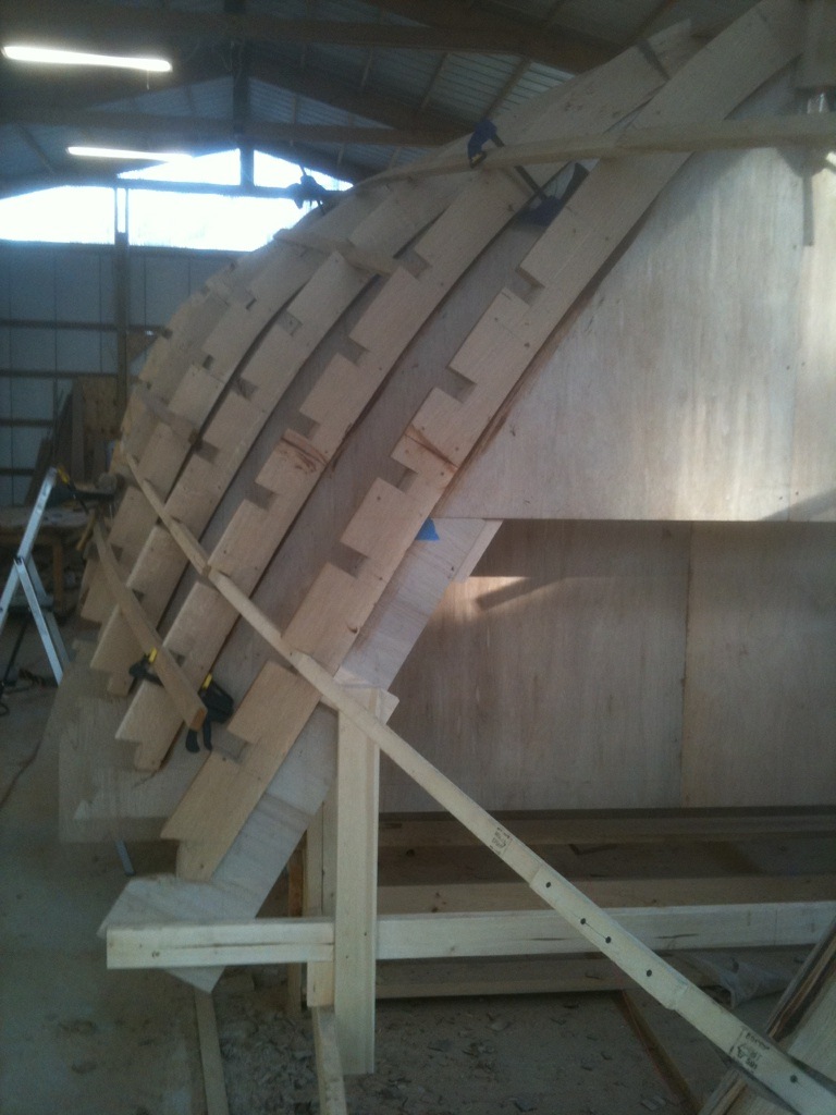
In this blog I am going to attempt to document the construction of a 49 foot sailboat.  I purchased the full size plans for this sailboat over 20 years ago when I fell in love with the lines of Glen L Marine's The Reliant.  The plans remained in storage for many years because I did not have the means to even start construction on this dream.


Usually I plow ahead on projects with out any thought as to how I would finish them.  Starting a project has always been easy for me so I tend to start ambitious projects without the means to finish them.  Not that I have never finished ambitious projects, I have.  But I have also left many projects unfinished in my life.  Such is the life of a man whose capabilities or at least his desired capabilities overreach his means both timewise and financially.  Back to the sailboat.  Starting this project seemed hopeless to me.  This project needed a building at least 60 feet long with high ceilings.  Where would I find such a building?  I'd never be able to afford to rent such a space and although building the boat outside is a time honored tradition, I knew that this would be a lengthy construction and it would be difficult to protect the project from the elements over a long period of time.  The extremes in weather in North Alabama can be brutal.  Temperatures range from the teens to over 100 degrees fahrenheit.  Humidity ranges from single digits to 100%.  It would be impossible to hold the structure true during the initial construction phases in this environment.  While an environmentally controlled space would not be necessary, a roof and walls to moderate the extremes would.  I've always considered myself clever (but who doesn't), yet I could not find a way around this first obstacle.  

This is the picture I fell in love with all those years ago.  How could anyone resist.


Time and life continued.  I left my business in the capable hands of my best friend and Gulf War vet, Alfred Kuhn, in order to finish up my physics degree (another of those lofty goals).  The physics degree turned into a Masters degree and before I knew it I was pursuing a PhD in Astrophysics (one of my most ambitious goals).  A few years later (2009) the economy went to shit.  Luckily Al and I saw the writing on the wall and closed our business about three months before hell broke loose.  We actually were able to close in the black and on good terms with our employees (finding new jobs for a few) and venders.  We're no super business men.  We are just two guys who pay close attention to demand in our industry (if you can call a five man sheet metal shop and industry).  We knew something was going way wrong and closed the doors before the economy bit us.  Now, we had no idea that the problem was endemic of the whole economy or how bad it would be but we knew enough not to go into debt to attempt to sustain our payroll through the winter.  It seems some of those experts on Wall street were too intoxicated with their own wonderfulness for their own good.  Oh, but I digress (this might be a bad habit that I'll need to work on).
One of my previous boat building projects with my best friend (Hamlet) in the bow. 

Anyway, that winter/early spring of 2009 when the fallout of the economic disaster was making itself know was the same time I was writing my PhD dissertation.  This is always a trial by fire for any academic discipline.  I was also very disillusioned by my advisor who had a very narrow view of my education and left me ill prepared and academically isolated (which I've mostly recovered from).  Throw in the dismal job prospects that come with a lousy economy and the breakup of a 13 year relationship and you can imagine where my head was.  I was frankly desperate.  Desperate for something to give me new life.  Then a contractor friend of mine needed a place to store his Bobcat (a modest size loader i.e. earth mover).  Since I had a large lot (1.5 acres) in the county and had an ulterior motive I said that I'd be happy to store it (did I mention how much fun Bobcats are to operate and this was not my first rodeo).  I didn't waste a moment and staked out the foundation of my new boat building shop that I would affectionately call my boat building building.  I was still a graduate student at the time and had no extra money living off about a $20,000/year stipend.  I did, however, own my own home which allowed me to spend a little extra here and there.  Once I had the 40X60 foot foundation built up with dirt and rock from earth moving projects that I volunteered for in the neighborhood I was able to order a truck load of gravel for the final leveling just in time.  The friend needed the Bobcat back.  Actually, I believe he needed to sell it but I have no proof of that other than that's what he eventually did with it.  With the gravel smoothed out and the foundation staked out with string I bought my first posts.  Two 16 foot 6X6 monster posts in fact. Not only were these heavy as hell but they are rather expensive costing around $50 a piece.  After a bit of good hard work digging a few big holes, these were set in concrete and I had the start of the boat shop.  As money permitted, I bought a post and installed it while occasionally purchasing 2X4's to string them together.  This was all occurring while I was finishing up my dissertation.  This is probably where I got the strength to finish that monumental task.  Finally the day came for me to defend my dissertation and I finally achieve the PhD that I had worked so hard on.  The defense went as smoothly as these things go and after a few edits of the dissertation it was ready for publishing.  I was now unemployed.  So I did what I do best and went into the handyman business.  I built decks, fences, refurbished houses, etc.  It was great work, great money, and often left me with a lot of spare time over the summer to work on the boat shop.  The final posts were installed, trusses went up and I contacted a friend of mine about roofing metal.  Even though I had the machine to make roof panels, it was actually cheaper for him to make the panels than for me to buy the material.  Next thing you know the roof was installed with the help of my trusty friend and partner Al Kuhn.  Most of the money I made from handyman jobs was funneled into the boat shop.  With about 10 guys and a few cases of beer, we were ready to pour a concrete floor. 
This is me pouring concrete.  Notice the tendonitis band on my arm, that's from slamming hundreds of 16d nails after sitting in an office for two years.  The body declines at idle.  Fortunately, I had been through this before and caught it early.  I also know how to cure it.  Constant stretches and I mean constant.  You have to stretch the muscle out or the tendon will never heal.  Drugs just make this worse by masking the pain.  That's Kevin in the blue shirt.  He's the neighbor that now has a giant building directly on his fence line and still thinks this is all a great idea.  He use to own a brick laying company and now owns a great tool sharpening company (Razor's Edge).  This may come in handy.  Mmmm.
Kevin making sure its going well.  The concrete is poured around the posts ensuring a strong structure.  There is actually steel attached to the posts to prevent high wind loading lifting the posts out of the ground.  The trusses are also bolted to the posts.
Half the pad is poured and leveled.  Waiting for it to set up enough for the power trow.  It turned out to be a long wait with a few trials and errors.  Being inexperienced it took me too long and the pad dried out before I could get it perfectly slick.  Probably should have kept it wetter but it turned out pretty damn good despite my ignorance.  The long wait also meant more beer which did not work in my favor.  
I'd never poured one that size and I had never used a power trow before but I did want a relatively   smooth finish.  The power trow proved fairly forgiving although I did not get a professional slick finish I managed to get a pretty darn nice finish, certainly nice enough for the shop.   Concrete floor poured, I elected to purchase material and make the metal wall panels with the machine that my company owned.  The system I used was better suited for wall panels than the roofing material used for the roof.  The next thing I knew, I had a boat shop.


The wall panels are going in.  That is Al Kuhn my partner in crime posing in front of what will be the doors.  And yes, those doors are too small for the boat to fit through when it is done.  The first thing people ask when they see the building is how will you get the boat out?  Really! Mmm, I hadn't thought about that (sarcasm flare).  Believe me, when the boat is ready to come out I will have no problem with taking a chainsaw to the end of that building and making what ever size opening I need.
Right after the concrete went in, the Madison county inspection department wanted to inspect the structure.  Oops.  Actually, they mostly wanted me to buy a building permit.  I complied and sent them some drawings and they sent an inspector over.  Everything passed except the trusses.  They were site built trussed which use to be common in these structures.  Anyway there was no way I was going to get an engineer to put his name on a truss that didn't come out of one of his reference manuals.  It turns out that the inspection department had recently change their requirements.  Early in 2009 after the economy went bust, the inspection department changed the requirements for needing a building permit for structures under $10,000.  You now needed a building permit for any work costing over $2000 (I suspect that they were trying to keep their inspectors employed during the housing slowdown).  I changed my tactic.  I was able to prove that I had started the project before the requirement change and that the project would cost less than $10,000.  A little lie that the inspection department was glad to swallow since they had no idea what to do with me and was glad to be rid of me.  The building was back on!