Moving forward: The Last Bulkhead Under the Stem.
It was time to place the last bulkhead. This one goes under the stem where the notch is located. Forward of this bulkhead will later become the chain locker and storage. To the rear of the bulkhead, will be the vee berth or forward cabin bed. It's shaped like an inverted "V" to conform to the tapering hull line. placing this bulkhead required building additional support to the jig because its the only bulkhead that floated above the jig. Extra caution was used to assure that this bulkhead was straight and level. Later I would find out that the placement for the deck clamp were mis-marked. Another mistake that I would have to correct. It required the addition of temporary support above (below in the current configuration. When using word like above and below I will refer to the boat as it will be once turned right side up.) This temporary support will be for the temporary bulwark clamp. Note the word temporary everywhere. Being temporary it did not matter that this support was not integral to the bulkhead. Once this final bulkhead was placed I would need long (~55 feet) lengths of 5/4X2" oak to make the longitudinal battens that span the entire length of the boat. These battens are what the actual hull planking will attach to. They also create the length-wise shape of the hull.
 |
| Bulkheads showing notches for the longitudinals and a few longitudinals temporarily in place. Thats my dog Hamlet in the background. He's been my bud for a long time. |
Oak in that length (55 feet) is not readily available. Actually I did find a place that specializes in extremely long pieces of oak and other marine grade woods for traditional boat building projects but the prices reflect the rarity of the wood (I'll try to find that link and post it here later). I knew that I would have to use shorter pieces of lumber and scarf them together. A scarf joint is a typical technique for joining two pieces of wood together. The simplest method would be to just end glue the two pieces of wood. This creates a very weak joint in that there is only a small patch of glue and any bending of the joint maximizes the moment at the joint. A scarf joint is created when the two boards end in long tapers. These tapers are then matched and glued together. This creates a large glued surface as well as having very little of the bending stress actually across the glue joint.
 |
| The two pieces of wood to be joined are labeled 'Battens.' The length of the taper is typically 10-12 times the width of the wood. I use clamping blocks to ensure even pressure along the glue joint. Wax paper is use to prevent the glue from sticking to the clamping blocks. |
Looking at the availability of lumber at mills that dealt with white oak I found it impossible to find 5/4" quarter sawn oak. I decided to go with rift sawn lumber since I was cutting the boards down to 1.5". At this width, dimensional stability would not be a problem and you can just think of it a quarter sawn boards 1.5" thick and 1" wide. With this decision made, it was much easier locating lumber. I found a guy who had two pallets of 5/4 rift sawn white oak. The lengths were around 7 and 8 feet long. Too short for what I needed but the price was cheap. Apparently no one wanted this lot and it had been taking up space at the lumber yard for a while. The best part was the lumber yard was about an hour up the road in Tennessee so I could get it myself and not pay any shipping. I purchase the lumber and started planing and cutting it to size. I scarf joined a few pieces together and looked at the results. I wasn't happy. Once you cut off the checks and scarfed the ends, the pieces were way too short. It would take too many to make up a longitudinal. Actually I ended up using the ones I had made for the temporary bulwark clamps. I ordered 16 foot 5/4" white oak from a lumber yard in Elora Tennessee.
 |
| A close up of glueing the scarf joints together. The scarf joints are matched up and epoxy is applied. A short clamping board is placed on both sides of the joint and pressure is applied using "C" clamps. Wax paper is used between the clamping boards and the scarf joint to keep the epoxy from sticking to the clamping boards. |
 |
| A wide shot of the scarfing process. I used an old craftsman radial arm saw and a jig to produce the scarf. you can see it in the upper right of the picture along with the floor timbers drying on the right. |
I was much happier with these lengths and started making the first longitudinals for the boat. With a few longitudinals I was able to clamp them bulkheads and mark out the notches. Oh the notches. The longitudinals need to be recessed into the bulkheads. This requires cutting notches that are asymmetric, beveled, and a bitch to draw and cut. There are 20 on each bulkhead. I will spend an inordinate amount of time marking and cutting notches. The best technique I found is to measure out the approximate placement of the longitudinals and then clamp one in place. I then mark the actual location of the longitudinal from the clamped piece. This is because wood does not always bend in a predicable manner and following the curve of the boat required a lot of wood bending. Later I was very careful in the selection of the wood for longitudinals so that the natural bends in the wood would closely match those of the boat (There is a learning curve when attempting a project of this magnitude. Things got easier as I gained experience).
 |
| This image shows the notching process. The longitudinal (top of the figure) is clamped in place and the notches are drawn from its placement and orientation. I used some cheap 1X2s to temporarily align the bulkheads as can be seen from the middle left to the bottom right corner of the figure. this figure also shows the cut away bulkhead that will be under the forward "V" berth. This is the only partial bulkhead. The remainder of the bulkheads will have companion ways cut out after the hull is complete. |
I used a straight edge on the edge of the longitudinals to project the notch onto the bulkhead. I then measured the depth (keeping it initially short of the necessary depth) of the cut on both sides of the bulkhead. I initially used a hand saw to cut the sides of the notch. I then used a skill saw to make several interior cuts and finally a chisel to clear out the notch. After ruining a few hand saws by hitting hidden screws in the bulkhead I started using a sawzall. I have a short throw sawzall thats great for precision work. The blade has a short throw back and forth. I used a very wide fine toothed blade. I usually started the cut with the hand saw and finished it with the sawzall. This was a good compromise between precision and buying a bunch of saws. Besides, the wood saws you buy at a typical hardware store (Lowes or Home Depot) are junk. I spend some time searching through them to pick out the best. You'd be amazed at the variation in quality between 5 saws of the same brand on the same shelf. A poorly made saw will cut crooked (or pull to one side in the middle of the cut) and there is nothing you can do about it. A nice saw costs way too much ($100) to wreck on a screw. I actually use the hand saw quite often during the construction of this boat. Its much more precise and produces a smaller kerf than any powered saw. Anyway, after I've chiseled a few notches clear down the side of the boat, I temporarily insert a longitudinal and check for straightness and depth. I purposely left the depth short so I always had to clear a little more material at the bottom of the notch. Often I would have to straighten it a bit or widen the notch a bit. All in all, it was (is) a time consuming proposition.
 |
| I'm king of the boat! I've placed several longitudinal battens and I'm notching out the bottom for the keel. Did I mention that those notches are a real pain in the ass? |
The longitudinal battens are temporarily laid into place once notches are cut the full length of the hull. I use West System epoxy to bond the battens to the bulkheads as well as two silicon bronze screws per bulkhead. The second lamination is bonded with West epoxy and screwed every six inches (staggered) with silicon bronze screws. It is these screws that I later substituted for stainless steel. These will be covered by the hull laminations and not subject to corrosion so I saw no reason in using the high dollar silicon bronze screws in this case. A local supplier (Huntsville Fasteners) actually has the lowest prices on stainless screws I've ever seen or heard about. They have smaller heads and no shank which is nice because I do not have to drill for the shank, only the countersunk head. Did I mention how cheap these screws were. The only downside is that later I had to shape the 3X3" shear clamp forward of the stem to make the hull fair. I removed as many screws as possible but the screws in the oak were tight and several heads were stripped or broken making removal impossible. The bronze screws are easily drilled out but the stainless screws are too hard. The hand held power planer doesn't really notice the soft bronze screws but the stainless ones will notch the cutting blades in a heart beat. I had to use a power grinder and grind down the screws below the wood and then use the power planer. Nevertheless I went through a set of planer blades (one thus far).
 |
| Battens spanning the entire length of the hull. The upper one (bottom of page) is the sheer clamp. Its composed of three lamination of 5/4X3" white oak. Only one is installed at this time. In this picture you can just make out the first layer of the keel laid temporarily into the wide notch at the bottom (top of the picture) of the keel. No more squinting. That's starting to look like a boat. |
 |
| Attaching the first lamination of the 3" shear clamp into the stem. The shear clamp needs to twist quite a bit to follow the contours of the hull. In order to accomplish that I made this tool that allows me to twist the lumber and holds it in place. This was also useful for some of the regular longitudinals as well. |
 |
| A close up of the longitudinal battens running into the stem. Note that the battens have to be recessed behind the edge of the stem to so that the second lamination falls smoothly into the stem without leaving a gap or overhanging. |
 |
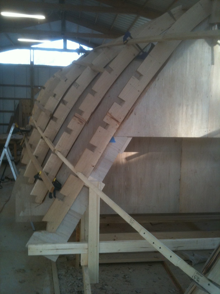
| Some of the second laminations of the battens going in on the port side. In this photo all three laminations of the sheer clamp are installed on both sides. |
Once I had a good start on the longitudinal battens, I decided to cut the plywood for the keel. The keel runs the bottom of the boat and is make of 4 laminations of 3/4" plywood. It widens considerably (16") midship and tapers fore and aft (6"). The keel lays in notches cut in the bottom of the bulkheads. I temporarily laid the first layer of the keel in place (It made a nice walkway up there). Floor boards, which are large timbers that the ballast keel is bolted to, will have to be fashioned and installed before I can permanently install the keel. I was still unsure of the exact sequence I was going to use in the construction of the hull. These keel pieces would lay around the shop for more than a year before I installed them (actually they are still not installed as of the writing of this page Dec 30, 2012).


No comments:
Post a Comment
Your feedback is very much appreciated.