The Transom
The transom is one of the most important pieces of a boat. Traditionally it is the weakest part and generally targeted during naval battles (this goes back to the very first naval battles that used rams as the armament and continued through the development of the cannon, on the other hand it probably didn't matter where a modern torpedo hit you). A failure in the transom has caused many a boat to go down. the transom keeps the boat true. The inherent sharp transition at the keel at the lack of timbers created the weakness. The canoe removed this weakness by making the boat have essentially two bows front and back. This design was utilized in large vessels as well as the common river variety that we are familiar. In fact, you see many modern sailboats with this double ended design today. Modern boat building techniques have largely reduced the liability of the transom to negligible levels. Nevertheless, I wanted to take particular care in constructing this part of the boat. I'm not actually sure that I took extra care in its construction because I've been taking pretty damn extra care in the construction of the entire vessel but I will say that I was extra aware during this phase especially with all the difficulty this part caused me. There are no patterns for the transom in the blue prints for this boat. The plans call for taking the shape of the transom from the actual work after a few longitudinal battens are installed. Really! I'm looking at the stern of the boat and seeing the longitudinal battens forming nothing resembling the transom. The port side of the boat in no way resembles the starboard side. The reason is that no two pieces of wood will bend around the hull the same. They all have slightly different internal tensions and, even though they might all start out straight, once you start bending them they will act different. Here is where I deviate from the written instructions of the plans (this won't happen very often). I decided to take the shape of the transom directly from the table of offsets. Of course only the projection onto the flat sheet is provided by the offset tables but I'm pretty good at projections and undoing them. Fifteen years working with sheet metal and creating finials and other decorative items out of flat stock well prepared me for this task. The table of offsets show a beautiful wineglass shaped transom. I spent some time transferring the lines to a pattern and voila' I had the transom shape I wanted.
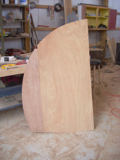 |
| Half the transom pattern shown upside down. Never make a full sized pattern of a symmetrical piece. You will never be able to get it perfectly symmetrical and these asymmetries will be magnified when you transfer the shape to the working piece. Instead make half patterns and flip it to draw the second half. This will ensure that the final piece is symmetric which is usually more important than getting the shape perfect. |
I butt glued some plywood together and cut the first layer of the transom out (I had to include a little extra material around the edges because these edges would later be beveled to the shape of the hull). The next and much more difficult part was placing the transom at the right angle and orientation at the rear of the boat. For this, I built a jig (I'm a big fan of jigs). Okay, so now the transom is on the jig and in position. I have longitudinal battens rough cut to length on both sides. I still have to install the frame on the transom (the transom frame will be a double lamination of 5/4" oak 6" wide). I still do not know how to install the frames and notch them for the longitudinal battens without cutting into the transom itself (which according to the plans is a no no). I decide to install a few longitudinal battens on the transom. This is very rewarding because now I'm starting to see how the wine glass transom completes the beautiful lines of this boat. After 3 or 4 longitudinal battens are installed on each side of the boat I decide it's time to tackle the frames.
 |
| The installed transom with the frame transitioning from the inside of the battens to the edge of the transom. The top of the picture shows the last of the frame pieces being glued in place with West System epoxy. I used the West epoxy instead of the resorcinol glue because resorcinol glue has no filling capability. This was a difficult glue-in procedure and I was unable to prevent small gaps in the work. West System epoxy will remain at full strength with gaps (actually strong clamping pressure is discouraged with epoxy) while the resorcinol glue will loose most of its strength if not properly clamped. I was able to make two notches in the frames before they were installed thus eliminating the need to notch the transom. See the top two notches. Actually I wasn't real happy with these notches which helped validate my decision to notch the first layer of the transom. I felt with the my use of epoxy, which was not a design requirement, I would compensate for any weakness imparted onto the transom. |
Building the curved frames with complex notches cut in them using measurements only was a challenge. I threw more than one piece of white oak into the kindling pile. Worse, once I had a piece I liked it proved impossible to actually put into position. There was no way to fit the finished piece onto the transom (I even tried a hammer). This was a three dimensional puzzle that I could not crack.
 |
| My First attempt at making the frames around the longitudinal battens. No matter how you twist or bang on this piece it will not fit due to the complex angles that the battens have as they meet the transom. I made a pattern out of paper that fits perfectly but paper is two dimensional and bends easier than wood. Time for plan 'B'. I make this photo after I had finished the plan 'B' installation so you can see the finished solution behind this frame fragment. |
Worse, the longitudinal battens were permanently installed so removing them was not an option. Time for plan B (it's good to have a plan B). I decided to move the frames to the inside of where the battens would be placed and then have them transition to their proper place once passed the installed battens. I would later use dead wood between the battens to fill in the frames. This would retain or even improve on the structural integrity of the transom while providing a way to attach the hull laminations. For the battens not yet installed, I would notch the frames and the transom in contradiction to the plans. I was pretty sure that the use of epoxy would offset any issues caused by cutting into the first layer of the transom (I must say that epoxy is not a miracle material and is no substitute for good craftsmanship. I've seen epoxy cover a multitude of sins and just wonder at how those sins will surface later down the road. Although it has saved my ass once or twice). Luckily, only one layer of the transom was installed so the second layer would not be notched. I have a thought to add a third layer to the transom so that there will be two un-notched layers on the transom. To date, I have not decided. I have figured out how to avoid this whole issue in the future. The transom should have been made out of temporary material with the permanent frame attached. The temporary transom and frame are then notched for the battens with the battens only being attached to the frames. Once the battens are installed, the temporary transom is removed, the battens are cut flush to the frame and then both layers of the permanent transom is installed. This sequence is easier than what I went through and conforms more closely to what the architect had in mind. Lessons learned and passed on to you.
 |
| This image shows the frame transitioning form the inside to the outside of the battens. |
 |
| After the dead wood is filled in between the battens. A few more battens have been installed in this photo. The hull shape is starting to look sweet. |
 |
| A close up of the inside of the transom showing the frame transition. This photo also shows the filler pieces in between the battens. The work looks pretty messy because I wanted to make sure the pieces were well epoxied. A bit of sanding will clean this right up. |

No comments:
Post a Comment
Your feedback is very much appreciated.