Monday, January 4, 2021

January 2021

 January, 4

Happy new year.  Here is hoping 2021 is better than 2020.  


A new year and a lot of work was done in 2020.  Over the Christmas holidays we did a lot of work both seen and unseen.  


Matching the curve of the bilge for this plywood composite  member which  will support the floor athwart members.  The curve height is measured at regular intervals and gridded out and marked on the plywood.  Brads are driven into the points and a flexible batten is bent with the brads.  Then just draw the curve using the batten.  Make sure the nails are outside the desired piece so the pencil mark is where it is suppose to be.

A perfect fit the first time.  That is rare.

The athwart members actually rest on a small shelf on the composite member. 

More white oak.

The first plywood flooring that will be under the cabinets.  I now have an actual horizontal surface to work on.  That will be nice.

I've finally worked out all the tankage that we will need.  We'll have to get all that fabricated and installed with the plumbing lines before too much ceiling (flooring) can be installed.  Both the black water and fresh water tanks will be constructed of 3/8" HDPE.  It is both weldable and strong.  We are going to have two 100 gallon fresh water tanks about 48 x 48 x 11 inches and two 60 gallon black water tanks about 30 x 20 x 14 inches.  

Jan. 10,

I'm working out the corner members for the deckhouse.  Geometry is your friend.


Getting the pattern just right.

Rough cut with the table saw.  Now to the hand plane and then belt sander

A good fit but it will not work on the actual boat.  I've got to match this to the angle of the deckhouse which is a bit more than 90 degrees.  So I'll have to further modify these.

The first one that is fitted to the corner.  That was a lot of work but at least I know now how to make the other ones.  I'm going to cut out a "Vee" on the underside to make these a bit lighter and easier to bolt onto the beams.


Very first one clamped in place.  

Second one clamped in place.  They are getting easier to make now.  It is important to make sure that the angles are exactly the same.

Temporarily bolted in place.  I've ordered stainless steel bolts for these.  When they arrive, I'll bond these with epoxy and bolt them.  Cutting that "V" in the rear (or inside) makes it much easier to bolt as well as creating a lighter structure without compromising strength.

The other side is bolted as well.

The forward deckhouse pillars must accommodate an angle closer to 100 degrees than 90.  So I have to redesign the forward pillars.

You can see that the "V" cut out is 90 degrees but the angle accommodated is much more.

I am getting the hang of it.  This one required only some minor adjustments after the first fitting.  

Do not worry about that large ugly knot.  This pillar is a third longer than it needs to be.  It fits great.

Both the forward deck house pillars in place.  You can see all four in this pictrure.

And the forward pillars are temporarily bolted in place.  The temporary nature is going to let me remove them when I want to fit the forward clamp that the deck house front will attach.  The same goes for the aft pillars.


January 24.

This side (port) looks pretty good.  I made a real mess of the other side (starboard shown below).  I'll spend some time fixing that side and hopefully it will turn out well.  The joint is flush with the outside as shown but on the other side it is recessed because the beam is thinner than the post.  This is by design to maximize the strength of the post.


January 26,
Well, I got the starboard side fixed.  The dove tail is recessed on the inside because the beam is thinner than the post.  I'm going to bevel the edges down and try to make it look better.  The dove tail joint fit okay but it needed a little epoxy filling.  I made a mistake when I cut this one out and did not take into account the difference in bevel from one side to the other.  The one above (the second one I made) turned out a bit better.

So this is the front of the deck house looking from the outside.  The beam is flush here because it needs to be.  It will be faced with 3/4" plywood and I'll make top member to mate the deck house roof.  The curved piece that is connecting the two posts is the piece of wood that I have been saving for some time.  It has a wonderful burled grain that will be lovely once finished.  This piece will end up just above our heads on the vee berth.

If you don't have lumber wide enough or long enough, make it.  This is the same cross member for the deck house except that it is at the aft end of the deck house.  This does not need to be a strong as the front,

How the beam above looks in full view before I cut the curve to match the deck.  This, like the one for the front will attached to one of my laminated deck beams and act as attachment point for the plywood deck house sides.


Jan 31.

It is the last day of the month and we've made quite a bit of progress.  As you can see I'm concentrating on the deck house.  I'm trying to get all the framing finished before finishing out the interior so I know where to frame the interior.  Also, I'm saving money to purchase high density polyethylene to build the water and black water tanks.  I need to complete all the plumbing before getting the sole installed and all the cabinetry is built upon the sole.  

The finished deck house front framing.  I'm just getting it rough sanded while I can get to everything.

I put it in place and tapped the bolts in and to my surprise it fit  perfectly.

And here it is from the front.

The aft beam for the rear of the deck house is temporarily clamped into place.  I then trace out the curve of the deck from behind.


I measured offsets to the curve traced from the previous step.   I use a baton to make a fair curve and cut one side. I then can use a gauge to score the other cut line.  I end up with a very lovely piece.


This is my favorite way of finishing the opposite face of a curved cut.  Once you have one edge made and finished (you definitely want to sand it smooth before you use the marking gauge) just make this simple marking gauge and slide it along an edge.  I use a small hole that just lets the pencil lead through.  


Clamp it back into place to make sure it fits and to mark the bevel cuts on the ends.

Everything temporarily installed.  I use the router to make a nice rounded turn over.  This is a nice touch and eliminates a sharp corner to bang your head.  I wanted to finish all the way around before I permanently epoxy and fasten it in place.  I might need to move it out of the way or take a piece down to modify something.  Keep you options open. 

This piece fitted to the deck house clamp will hold the deck house sides in place.  There is a lot of twist in this piece of wood and as you can see where it meets the forward post, there needs to be a bit more.  I made a quick test and the extra twist is easily achievable and I'll make sure we get it right when it is all bonded in place.


I managed to get the entire port side fitted in place and even got  half of it drilled and screwed with temporary fasteners.  Again, I use drywall screws because they are cheap and when I later permanently install these pieces with real screws, I have not destroyed the hole.  Drywall screws have a large pitch and very sharp threads so they go in quick and leave the wood in good condition for the real fasteners.  I also use longer permanent screws so they grab onto a virgin part of the hole.

The front part is all glued up and I even cut out and positioned the front of the deckhouse.  


Monday, December 7, 2020

December 2020

 December 7,

Work on the interior continues.  On Saturday morning I remade that double door stop member that I was not too happy with.  There was just not enough width for the 1" (2.5 cm) doors that I was planning on building.  I had to make it out of two pieces due to its cross section.


The notch is for the 1/2" plywood wall.  On either side is the door stops going the opposite direction.  Now there is plenty of room for door hardware and the shape will be continuous around the door.


These are the casings for the top of the doors.  The curvature matches the deck cabin curvature.  The pattern in plywood is on the right emphasizing the curvature with is not much.

In order to dado the channel I added a bump plate under the saw blade so the curved pieces would have the proper dado depth along their length.

Saturday afternoon and Sunday morning I continued to work on the ventilation strips that go under the ceiling (the interior sides of the boat).  I also fitted more of the tongue and groove bead board to the starboard side.

This is an image of the starboard side of the 'Vee' berth.  Ventilation strips go along the side from below the berth to the vents at the top.  

Dec 19,20

I finally figured out how to tackle the sole.  After scribing leveling marks along the bulkheads to either side of the mast step girder, I installed oak strips to take up the sole material.  The sole will be 3/4" plywood under the lockers, berths, etc. while I'm planning on using quarter sawn southern yellow pine accented with black walnut for the exposed sole and companion ways.  Why? because I have the black walnut and we live in the south where southern yellow pine is plentiful and inexpensive not to mention beautiful when quarter sawn.  

Using plywood in the unexposed portions of the sole is easier and cheaper than laying planking plus I can go ahead and install that part of the sole without worrying about pluming and system runs (they will be accessible from the planked part of the sole which will have removable panels.  Once the plywood sole is installed, I can build out all of the cabinetry.

On the bulkhead at the top of the photo, you can see the  athwartship oak strip.  I've put a temporary nail into it and run a line between the two bulkheads (the other is not shown).  I am then able to rough measure the members which will support the sole.  You can see one dry installed in the middle of the picture.  This one actually runs into the longitudinal.  Some of them will actually run all the way to the hull.  There will be an intermediate support from a lower longitudinal to the athwartship members holding up sole.  I'll install these last so I can perform a final leveling of the the sole by tweaking the height of the middle of those members.  I'll take a picture and show you later.

The next one notches into the longitudinal and continues to the hull.  Notice that there is just a little bit of space between the red line and the member.  Always set the line a hair high because you can not tell if the member is at the line or pushing it up just a bit but you can gauge the space between the line and the member.

Looking at a few more of these temporarily in place.

All of the support members for the sole in the starboard cabin ready to install.

All of the support members for the sole in the port cabin ready to install.


Monday, November 16, 2020

November 2020

 November 16,


We have not posted in a few weeks but work continues.  I finally got that mast step girder in place permanently (hopefully).


The beam is sitting on rubber flashing that should prevent condensation off the beam from getting between the beam and the floor boards or spacers.  The bulkhead plywood exposed ends are epoxied.  That is plywood's Achilles heal.  I'm using galvanized lag bolts to mount the forward part (to match the galvanized beam), the aft end will be held in place by the 1" (2.5 cm) 316 SS keel bolts.  Notice the holes drilled in the top part on either side every 16 inches.  The sole girders will mount there using 1/4" bolts.  

I'm using this inexpensive pine tongue and groove bead board for the ceiling.  Note the vents at the top.  After it is all cut and installed, I'll take it all down and prime these boards on all four sides.  

This is my recently purchased load of plywood.  This should be enough for the interior.

This is the water closet.  The shower pan is in the foreground while the head will be located on that shelf just above.  

Now I have to figure out how to get three doors into that small space.  I'm dealing with a chicken and egg dilemma.  I'd really like the deck house to be installed to build out these interior walls but I really don't want the deck house in my way. This is going to call for some careful planning. First let's design the door casings.

This is a prototype door casing for the bulkheads.  The doors will be 1" (2.5 cm) thick which is the thickness of the flat part of this piece of molding. 

I set up this dado on this 45 year old radial arm saw that use to belong to my father.   No carbide cutters back then.  Still, the blades are sharp and they do a good job.  This freed up the table saw for cutting out the stock.  

A whole stack of door casings or bulkhead molding depending on how it is used.   These are about 80"(203 cm) long.

This molding is designed for the end of a 1/2" (1.25 cm) plywood wall (note the 1/2" dado) and has opposite door stops on either side.  One for the shower door and one for the vee berth door.  I'm thinking that it is not wide enough and I'm going to have to make it out of two pieces.  I should have made a sample first.  


Monday, October 12, 2020

October 2020

 October 11,

Not much has gotten done over the last two weeks.  I've been at the hospital looking after my dad.  Hopefully he will be home in the next few days.

I did manage to get a little work in over the weekend. 


Looks like the right angle drill is the perfect size for cutting the 1 5/8" (4.13 cm) limber holes between floor timbers.  5" thick white oak is not easily drilled though.  It will be a bit of work.  I'm using that diameter because I have a source of copper tubing that, if I choose, I can hammer into the limber holes to make them more robust.   I also started drilling limber holes in the longitudinals between floor timbers.  I'm only drilling 1/2" (1.25 cm) holes for these.  

Cutting the "H" beam with an inexpensive die grinder with a cut-off blade.  Be careful when cutting something that large.  Keep your face out of inline with the blade.  Those blades can shatter and send shrapnel right through your head.  If it wasn't for COVID 19, I'd wear a face shield but they are in high demand right now.  At the very end my disc jammed and sent fragments into the wall behind me.   If my head was in the way, I don't think it would have slowed those fragments down much.  Scared the hell out of me.  I also jammed the grinder so bad it might not be worth repairing.  I was so close to being done with the cut that I was able to finish it off with a few minutes of sawzall action.


I also made a mockup of the "H" beam that will be the mast step girder and support for half the ballast keel.  I used the mockup to plan a sequence of actions that will maximize the accuracy of the installation.  Later, the ballast keel will be lifted to the hull and those 1" (2.5 cm) threaded rods had better fit perfectly.

October 26,

I've identified several holes that need to be drilled into the "H" beam prior to the galvanizing process.  
  1. 1" holes for the ballast keel
  2. 1/2" holes for lag bolts that will hold the "H" beam in place forward of the keel bolts
  3. 3/16" holes for mounting wood to the side in order to mount sole framing
  4. 1/4" holes along the webbing to mount the gray water, black water, and fresh water lines
  5. 1/4" holes port and starboard to electrically connect the beam to the bonding rods
The bonding rods that run the length of the boat on both the starboard and port side will be connected to the mast step girder via copper cable.  I'm going to use copper ring terminals that I'm going to tin myself in order to isolate the copper from the zinc of the galvanizing.  I'm also planning to use a lead sheet barrier between the mast foot and the zinc.  I don't want to loose the zinc on the beam to any unnecessary galvanic interactions.  

October 28

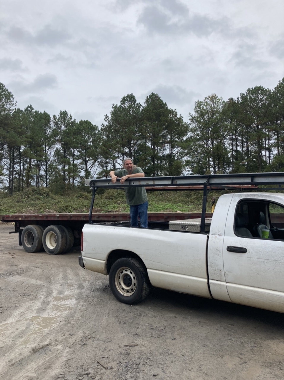
Took a trip down to Hansville Alabama (1 hr 15 min.) to visit Kennedy Galvanizing.  They were able to galvanize the mast step girder in the same day for a very reasonable price.   They loaded it up on the truck with it still pretty warm.  Now we got to get that thing in the boat.


About to off load that beam.

Laura taking a selfie in front of the galvanizing tanks.


See ya later steel beam. 


A few hours later it is sitting outside waiting for us.

With my name on it.

Yep, still very warm.


Securing it for the ride back to Huntsville.

Someone else's parts.

Setting up rigging to get the beam in the boat.  The beam weighs 250 pounds  (113 kg).  I have one chain hoist over head and one horizontal to control the lateral movement.  I had just enough swing so there was no need for muscle. 


The galvanizing work is scrutinized by Fig.
Preparing the rigging.  This chain hoist will let the beam swing onto the boat.


Coming up the side.  I have some old lumber protecting the side of the boat.

Almost there.
A big smile because the hard part is over.


It is in!

My wife Laura.  She is ready on the chain hoist.   Actually, I could not do this without her.

In the boat after not that much difficulty.  You can see that it will eventually be moved to those notches in the bulkhead.  
And this is where it lays.  


Drilling those 1-5/8" holes are a real pain.  With Laura applying leverage, all I have to do is guide the drill.  Easy as can be with two.  Hard as hell with only one.


Halloween beer witch.

I used some 3/8" exterior grade bead board plywood here for the ceiling because frankly it's in the back of a locker and will never be seen.  This wood is left over from a home restoration and was previously primed with exterior grade primer.  Unfortunately, the primer was rolled on and I hate roll texture so I sanded it smooth with a belt sander.  Actually, the surface of this plywood is not that great so I'd have to sand it anyway.  It will look good painted.


On the far side is that locker shown above and on the near side is the lavatory.  Again, for the lavatory, there will be none of this plywood showing since it will actually be the back of closets above and below the lavatory.  I'm going to pull all of this back out and prime both sides before final installation. 

After removal, priming all sides, and reinstalling.


I used roofing tar paper to make patterns for the plywood.  You can tell the rather complicated shape this piece has.


Preparing to install the ceiling.  I've added 5/16" vertical spacers so that when I plank the ceiling, I will have good air flow from the bilge up to the gunwales.