Monday, December 5, 2022

December 2022

As I mentioned earlier, all waste water plumbing will be schedule 40 PVC and all fresh water will be PEX.  PEX is chosen for its flexibility and durability and the PVS is chosen for its durability and price.  I think PVC is generally not used in pleasure boats because it comes in stiff straight runs and not well suited for the curved surfaces of a boat.  It also requires glueing together (actually chemically welding) and can be a bit of a pain to cut correctly.  Or at least I thing these are the reasons builders don't use it on pleasure boats.  It is much much cheaper than sanitary hose, lighter and I suspect PVC is more impervious to odor than conventional sanitary hose.  I've worked with PVC quite a bit on residential projects.  I've also learned that it can be bent to pretty tight curves given a bit of finesse. The trick is heating the pipe to the right temperature and not trying to bend it too much in a single heating cycle.  I found this out when I built a steam chamber out of 4" PVC pipe back when I built my first canoe.  The steam chamber worked great but it started to sag in the middle. I thought at the time that knowledge would come in handy. Sure enough, I was able to bend 1.5" PVC to the curvature of the side of the hull (see pictures below).  Cuts still take some trial and error in the tight spaces of the hull of a boat.  Dry fit the pieces together and don't glue up too much at one time.  Remember that when you add glue to the joints being joined, they slip a bit tighter that they do when you are dry fitting them.  As for transitioning to marine fittings, such as pumps and through-hulls, a 1.5 - 1.25 rubber transition bought at your local hardware store works perfectly.  These rubber transitions are tough and made to last forever.  They also add some vibration isolation and flexibility when attached to pumps and rigid fittings.  All tank fittings are designed to work with threaded PVC fittings or glue in PVC fittings son no weird transitions needed.  

 Dec 4,

It's almost time to say good-by to the holding tanks.  Soon they will be covered by the sole.  I still need to add a vent to each tank.  I have the fitting but have not decided the best way to proceed. 

Working through the rough plumbing.  The pump-out is a 1.5" PVC schedule 40 pipe starting at the bottom of the tank connector and drawing straight up and around the starboard tank.  It then encounters a "Y" where the straight part continues to the pump-out port on deck and the branching part goes to the waste pump and up through a vented loop and back down to a through hull fitting.  The vented loop portion and through hull fitting are not shown.

Cut our some flooring that will go under the cabinets in the galley.  You can see the "U" galley if you ignore the 12"x24" temporary piece that is in place in the middle so I can stand and pretend to cook. Plumbing access holes are not yet cut out of the sole. 

Preparing for laying down the fresh water tanks. These are aluminum "U" panels that wrap around the floor boards with 30# asphalt impregnated felt in between.  The tanks will lay on these. No condensation issues here.  

Tanks in!

I don't need any super expensive sanitation hose.  Schedule 40 PVC is superior and cheap.  Oh, and you can bend it after heating with a heat gun.  

Yes, the heat gun worked very well for the above bend.  The technique that I used for this bend is that I held the heat gun so that it blew hot air into one end of the pipe.  This heated the pipe evenly around the circumference of the pipe but tended to over heat the pipe on one end as apposed to the other.  For short lengths this is not a problem.  For intermediate lengths, you might want to heat both ends, one after the other.  The pipe cools very slowly once heated so cooling is not a problem.  For this bend, heating more on  one side than the other actually worked in my favor.  For long runs and gentle curves, I'll try heating the pipe externally and slowly working the bend I need into the pipe.

The tube to the deck goes to the deck pump-out.  The "Y" goes to the over-board pump-out (pump shown) via a ball valve so I can replace that pump without stinking up the entire cabin. There will be a loop up under the deck before the plumbing goes back down below the waterline to a through-hull.  I need to get the ceiling in first because all of this will mount to the ceiling under the settee. 


Wednesday, November 2, 2022

November 2022

 Nov 2,

I picked up the new bulkhead fitting today.  The last piece to complete the tanks.  Unfortunately, I'm going to be out of town this weekend.  I'm hoping to get a little tank welding in anyway.

Nov 5, 

I have finished the second freshwater tank.  Woo Hoo! I'm going to get the holding tanks finished before I put those tanks in the boat though.  


Monday, October 31, 2022

October 2022

 October 30,


Well, I was out of the country for most of the month.  I had a work trip to Johannesburg South Africa and my wife and I stopped off in Paris on the way back.  We replay had a great time and learned a lot about South Africa.  Beautiful country and very nice people.  

I managed to get some work in this weekend on the boat though.  Putting the finishing touches on the tanks.  Getting them to not leak was not the end but, luckily, the end of the trouble.  Everything since has gone fairly smoothly. 

I'll have some photos soon. 

Final fitting of the top of the fresh water tank with the access port fully populated with  bolts.  Those took some time to install.  

An actual finished fresh water tank.  The other ready to have its top welded on.

The holding tanks (or black water tanks) with their tops fitted and ports drilled for access and plumbing.  I've got one of the floor beams in place to check the fit. I had to order another bulkhead fitting to accommodate the shower drain from the shower sump pump.  Originally I had it plumbed into the pump-out tube between the tanks but I figured that that would not work well when pumping out the tanks.  There is no guarantee that the sump pump would hold the pump-out vacuum and I'd have to put a valve on the line to make it work correctly.  The new plan is to run it to the top of the tank using a bulkhead fitting.  There is just enough clearance. 


Wednesday, September 14, 2022

September 2022

 September 11,

I was able to correct the leaks in the fresh water tank.  I initially had three leaks.  Two corners and one bottom seam.  One corner and the bottom seam were fairly straight forward to fix. The last corner proved to be a real problem.  I tried to fix it multiple times and ended up with a mess.  Since I was unable to get to the problem and was now dealing with a mess, I cut out the entire corner and replaced it.  Solved the issue and the tank no longer leaks.  Investigating the bad corner, I noticed a void in the weld that might have been trapping water or air that prevented the new weld to seal properly. Whatever the reason, it is fixed now. 

I cut the corner out and replaced by a solid chunk of HDPE.  

I also attached the plumbing to the second freshwater tank and performed a leak test.  I have two corners leaking and the first few attempts to fix these failed.  It was late and I was tired, so I needed to put the work up and think on the best way to fix these corners.  Hopefully, the second tank won't be as miserable to fix as the first. 

Sept 20,

Making some progress with sealing the second tank.  I still have a very small leak in a few places.  Every step forward seems like two steps backward sometimes but I'm making progress.  I also worked on the brackets that hold the plumbing in place on the bottom of the tank.  No unsupported plumbing on this boat.

One assembled in the background and one in pieces in the forefront.  

And this is how they attach.  That ball valve and connection to the tank is now well supported.

Both tanks being filled near full to check for leaks.  Almost 200 gallons of water (1500 pounds). A 24 hour wait reveled some very small drips around some of the seams.  These very slow drips can be ground down and re-welded without draining the tanks.  The act of grinding the drip area down, temporarily stops the leaks and lets me get a good weld in.  Unfortunately, there are occasionally underlying conditions that make these leaks pretty persistent so I keep trying until I get a 24 hour leak free period.  The tanks have been filled for a week now and I've addressed most of the issues. I had a new leak show up this morning after 6 days.  It is such a slow drip that the water almost evaporates before I can see it. Almost.  Well, that will be easy to fix. 

Obviously, I've made a tactical error in the design of these tanks.  Most importantly is the difficulty in welding the corners where three planes (two sides and the bottom) come together.  If I ever make a tank again out of HDPE, I will mold the sides like I did for the black water tank connector (Vee groove half way through the thickness of the HDPE, add heat and bend to a 90 degree corner.  Then weld inside.). I believe this would have eliminated 95% of all my issues with these tanks.  I'm not terribly happy with the workmanship on these tanks.  The re-weld work is not that pretty.  At least the inside will be smooth and clean and the tanks will not leak. To prevent any nooks and crannies where dirt can collect, I've ordered some food grade silicone that is formulated for tough surfaces.  I'm going to fillet all the inside corners with the silicone to make a super smooth inside to help keep the tanks sanitary.  I insist that I am not using the silicone to stop any leaks.  All leaks will be fixed by welding the plastic.  However, if I happened to miss a very slow leak, the silicone will act as a long lasting insurance policy. 

Friday, August 12, 2022

August 2022

 August 6,

There was really nothing to do but to cut out that connecting channel and start over.  I removed the tanks, cleaned up the old welds and made a new connecting channel.  I had just enough room to weld the connecting channel to one side with the tank removed and slide it into place when done.  This allowed me weld both sides and ensure a water tight joint.  I'll still have to weld the other (port) side when the tanks are in place. 

The new connector tube with plumbing attached.

Refitting the tanks.

All back together.

Well, I still have a very small leak along two seams.  It took me a few times grinding the seams down and re-welding to reduce that to a small weep.  Not much more than a sweat bead.  The amount of work done thus far is ridiculous. I think this is my first not so happy outcome.  My intention is to seal all the welds with epoxy.  I'll have to clean the tanks with alcohol and rough up along the seams with some sand paper.  I've already tested the bond strength of epoxy on the HDPE with the proper prep and there is a nice bond. Specifically, I'm going to mix up a quart plus of epoxy and pour in the lowest part of the tank that has the connector tube.  Basically, I'm flooding the area that is susceptible to leaking.  If I can get about 2-3 mm of epoxy floating on the low side of the tank, it will warm up and seep into any voids and small cracks permanently sealing the tank.  I hate to cheat like this but I just can't get the tank fully sealed otherwise.  If the weld is not perfect, you get a cold joint.  The conditions really have to be perfect and that is very difficult welding the connector when the tanks are already installed in the bilge. Luckily, the water tanks will be fully welded and tested outside of the boat where I can make better repairs if there is a leak. Specifically, I'll have full access to all welds on the inside and outside of the tanks.  

Aug 19,

The holding tanks are sealed and almost ready to have the tops put on. I've decided to go ahead and lay all the plumbing runs before I locate where the two main 1.5" lines from the head will attach.  These two lines will carry waste from the heads and the three wash basins in the cabins. The Kitchen sink will also drain into the port waste line.  All of that water is gravity fed into the tanks.  The two shower drains go to a closed sump and are pumped into the tank.   I'm also working on the freshwater runs so I can locate where the water will drain from those tanks.  

The brown lines represent the waste water system and tanks.  The blue and red lines are the fresh water system.  Blue for cold and red for hot water.  It's a rough design but enough to get started. 

The fresh water tanks can be tested for leaks on a bench top instead of in the bilge.  Much easier.  I did have some issues in the corners where all the HDPE faces come together.  So there was some grinding and rewelding at those places.  I'm going to go ahead and do the same for the other tank before I test because there is an obvious weak point at those corners.

The drain for the fresh water tanks is attached via a 1/4" thick EPDM gasket and set in a small well to allow the tanks to fully drain.  A 1/2" PVC elbow is screwed into the tank bulkhead fitting and a ball valve is glued to the elbow.  Each tank will have its own valve so they can be individually shut off.  Half inch PVC pipe will run to the edge of the tank supported by a bracket (not shown) and then we convert to 1/2" PEX.  The PEX will run to a tee which connects both tanks and then runs aft via 3/4" PEX to the pressure pump.  3/4" PEX is run all the way to the water heater (under the sink) and forward to where it splits and reduces to 1/2" to go forward and to starboard to the separate wash rooms.  At the water heater (tankless powered by propane), the cold and hot water tees to the kitchen sink.  The kitchen sink drains directly into the black water tanks at a junction that receives the waste from the port head and the port cabin wash basin and the vee berth wash basin.  The starboard was basin and head drain into the starboard black water tank (holding tank).  All of the above waste lines are gravity fed.  The two showers drain into a well pump and are pumped up into the black water tank using a tee at the tank connector where the pump-out is connected. 

Tuesday, July 12, 2022

July 2022

 July, 10

I've spent some time cutting the tongue and groove "V" boards for the ceiling while I wait until the parts come in to finish the tanks.  Originally I was going to weld all the fittings onto the tank using HDPE pipe.  As it turns out HDPE sheet and HDPE pipe are not generally weldable to each other.  I've since ordered some impressive looking bulkhead connectors that have 1.5" NPT threads on either side.  The large ones for the black water tanks have arrived and I was able to take measurements to make a connector tube to connect the tank on the port and starboard side together.  On top of this tube, I will put the pump-out tube via one of those bulkhead connectors.  I did some experiments to figure out how best to make this tube to connect the tanks.  I used a "V" bit in my router and cut a 90 degree "V" where I wanted to bend the HDPE sheet 90 degrees.  I did not cut all the way through.  I left an 1/8" and used the hot air welding gun to soften up the joint so I could bend it to shape.  As I got to about 75-80 degrees, I had a narrow groove that I was able to heat to welding temperature and then close the gap to make the 90 degree bend.  I held it in place until the HDPE cooled.  Then I added a weld down the inside.  In this way, I was able to make a square tube with only one real seam.  Also, the rounded corners look real nice.

I am holding the tube in a jig to ensure that the sides stay at 90 degrees while the weld joint cools.  I just made the next to the last weld.  

The completed tube that will connect both tanks across the centerline of the boat.  The  pump-out pipe will connect to the top (side as pictured) of the connector tube since that is the lowest place in the tank system and equally close to both tanks.


July 30.

This is how the connector tube is suppose to fit.

View from inside the tank showing how tight I've fit that tube,

A view from the other tank. I'll cut a groove where  the weld will go.

This will be the pump out tube in the middle of the connector.  It is the lowest part of the tank.  

This is the external gage that will let me know how full the tanks are.  Nothing to get fowled here.

Final installation and welding of the connector tube. I've put rubber flashing over the longitudinal where  the tank will sit.  This will keep condensation, from the tanks, off the wood.  I did the same under the I-Beam that acts as a mast step girder as well as bolts to the ballast keel. 

I like to illuminate my work.  

Filled with water.  Wait... is that a leak!  Actually I had a leak on both sides. This one was easy to fix.  The leak on the port side was a disaster.  I spent an entire day working on it and just could not get it fixed.  Finally, I stuffed rags in the limber holes and flooded the section of the hull where the tank is hoping to see water enter the tank at the leaks.  It's pretty tight there so it really did not take much water and it only took a little to see where water was coming into the tank.  A lot easier than figuring out where the water was coming out of the tank.  Even knowing exactly where the leak was, I was unable to fix it yet.  I completely ground down the welds and re-welded three times.  I still have 3 small beads of water percolating up from very small pin holes.  I think my issue is the dampness of the wood beneath the tank.  When I try to re-weld, moisture (steam) seeps up creating gaps in the weld.  I've marked the small pin holes and I'm going to let everything dry out over the next few days and try again.  At least I have a rather easy method of finding the leaks.  


Friday, June 10, 2022

June 2022

 June, 10

My next two goals are:

One, finish up the chain locker.  Two, finish up the black water (holding tanks) and fresh water tanks with rough plumbing. 

So I've been buying through hulls, seacocks, elbows, vented loops and deck hardware. I also have a pump to empty the black water tanks at sea.  I went with Groco for everything below the waterline. Bronze with flanges.  With quite a bit of searching I found some good deals.  For the vented loops, I went with Marelon from Forespar.  Failure in a vented loop is unlikely to sink my boat and will be noticed fairly quickly since they are above the waterline.  I've also decided that the 'ceilings' need to be installed first with cutaways for the seacocks.  This will present a nice clean surface to mount all the plumbing behind and above the cabinetry.   The ceilings are just the inner walls of the hull and I've chosen southern yellow pine tongue and groove with a nice bead.  I've found some very nice clear stuff from Home Depot of all places.  Actually, it's the nicest stuff I've found and you'll never hear me promoting Home Depot for anything else.

Other considerations:  I've purchased some sending units and gages for the potable water tanks but I do not have a solution for the black water tanks.  I'm thinking visual inspection might be the best approach. The combination of what is in the tank (salt water and poo) does not bode well for and device in situ and the remote sensing devices are terribly expensive.  I'm still thinking on that. 

Further considerations:  Wire runs for the pump out pump, fresh water pump, and sump pump will have to be made as well. 

Most of the pieces for the chain locker have been fabricated and fitted with the exception of the bottom floor which is actually rather small.  One complication is that I have to have a drain for this part.  I found an extra long 3/4" Groco through hull fitting that should make it from the hull right up into the bottom of the chain locker without any additional fittings.  This is important because once it is installed there will be no access for maintenance.  When I glass the chain locker, I'll glass in the drain at the same time. I should end up with a large, sealed chain locker above the water line with a nice drain.  When in port, I'll be able to wash the chain down with fresh water.

June 11, 

I've been able to put some more time in on the chain locker.  This space is proving to be very difficult to make. I'm almost there though. The floor is 3/4" (19mm) plywood and must be curved around the stem.  The sides are 1/4" (7mm) plywood. I will fiberglass the entire area to make it water tight and strong enough to take the abuse of the chain. 

I finally got that piece over the stem to fit.  I just have to put in the little trapezoid in the back.

First attempt at the trapezoid failed.  I've been so pleased with the symmetry of the boat.  Most pieces I make for one side fit pretty well on the other.  I usually have to do some detail trimming but I've been impressed with how symmetric the hull is. I did work hard at it. This is an example where I'm off. And not off in a bad way. This piece requires precision.  It must be level and fit all the beveled surfaces it comes in contact with.

Using the first piece that didn't quite fit correctly, I was able to make one that fit very tight and was very level.

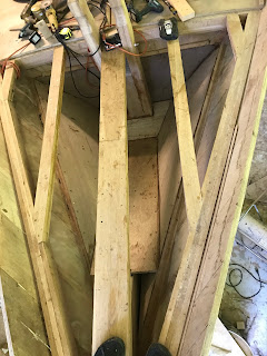
An overall view of the chain locker.  The back panels and bollards made earlier will fit through the trapezoid floor so I'm not quite done yet.  

June 18,
Everything is cut out and fit into place.

Now for the drain.  There will be no access to the  drain when this is complete so I wanted a through-hull fitting that was long enough to go all the way to the chain locker.  This bronze one from Groco is 5 1/4" long.  Just long enough.  I used the block of wood at the top of the photo as a jig to drill the hole.  Even then, I was unable to have the through-hull fitting perfectly flush to the hull. I'll have to build out a little with epoxy to have it seat properly.  I think this is a fair compromise for a permanent solution.  The end of the through-hull will be ground level to the bottom of the chain locker prior to glassing everything in. 

The bottom of the bollards are attached to the stem by a 3/4" 316 stainless threaded rod. The bollards also act as a structural member creating a triangle between the stem and the bow sprit. In order to get the threaded rod installed, I had to drill a 1" hole through the hull. It was impossible to fasten a backing plate on the inside of that hole, so instead, I epoxied the backing plate and held it in place with a bolt and wedge.  The bolt and wedge will be removed when the epoxy is cured.

The chain locker epoxied and screwed in place.  I have to fill all those screw holes now.

The chain locker drain on top and the filled access hole to install the 3/4" stainless steel threaded rod is below.  I used un-thickened epoxy to coat the inside of the hole so I'd get an optimized bond.  Before that epoxy was cured, I used very thickened epoxy to fill the hole making sure that all the air bubbles were squeezed out.  The thickens epoxy will chemical bond to the thinner epoxy and make an optimum bond to the hull.  Later I'll grind away the top layer of glass around the hole and replace with new glass. 

June 24

Taking a break from the chain locker (It's almost ready to glass) and fitting some more ceiling in the main salon.  Once fitted, I'll take it all down to be primed and have a first coat of paint.  All the ceilings really need to go in before I make much more progress.  I'll need to do a little rough wiring for the pumps but all of the plumbing needs to go on top of the ceiling and under the cabinetry. 

A little tough making those curves.  I experimented below the cabinet level on two different approaches.  One is do away with the tongue and cut the curve so it fits flat.  The other is putting a break in the middle of the run.  Since the curvature gets worse below the cabinet level I've decided to go with the break for two reasons.  1) It actually looks nicer (not that that matters since it is unseen but that's how I role) and 2) I can take advantage of shorter pieces and save money.  These boards are $20/each. 

I need to get those ceilings down to below the floor boards (not yet installed), run wiring to the major pumps (shower, waste, fresh water), and lay in the rough plumbing with the waste through hull.  Then the under cabinet sole can go in.  I've decided to use the 3/4" plywood as the sole under the cabinetry and I'm hoping to use quarter-sawn southern yellow pine for the companion ways.  


June 30,

The port side ceiling fitted and temporarily installed.