Thursday, August 15, 2013

August 2013

I have been very busy this month and although I have done a bit of work on the boat, I have not had time to tell you about it.  I'm going to go through the process of installing one of the cold molded strips on the hull not that I have gotten the hang of it.  

The fist thing that is done is the strip is laid onto the hull close to where it will be installed.  There should be at least 1.5" between the new strip and the installed adjacent strip.  There should also be about the same space at the to as the bottom.  The gap in the middle will be different than at the middle. Hold the strip in place so that it can still move around.  Start clamping at one end and move toward the other making sure that the strip is laying flat against the longitudinal battens.  You may have to adjust the entire piece and restart the clamping pressure if the strip wanders to close or too far away at the opposite end.
Strip clamped into place.  There are fewer clamps between the strip than on the outside because that is where I need to mark the cut line for the strip.  Use enough clamps so the strip lays flat on the longitudinal battens.
I've modified an old marking gauge for the next step.  I drilled a hole in one and cut a slot so that a pencil will fit securely in place.  A screw and wing nut holds the pencil in place.  The marking gauge is slid along the last installed strip while marking the temporarily installed strip.  The idea is that you want the these two pieces to fit together so you mark an equal distance from between the two.  Make sure the marking gage is set slightly wider than the widest gap between the two pieces.

Checking that the marking gauge is set just wider than the wides gap between the two strips.

Sliding the marking gauge along the gap to mark the cut line.  Normally I use two hands for this.

A power saw was used to cut the waste off the strip.  I cut to just before line.  I then use the hand plane to finish the cut. This leaves a beautiful clean edge.  
Once the strip is cut and finished, I re-clamp it in place.  I usually have to use a few temporary screws to hold down the edge where it mates with the last installed strip.  I make sure every thing fits nicely and that there are no overly warped places of gaps.  These are caused by either forcing the strip to bend closer to the installed strip or by a strip that is too wide.  Reposition and remark or rip the outside down an inch.  Make sure you cut the outside and not the nice curves side you just made.  Look for gaps that are larger than your thumbnail.  These usually can be fixed by a little hand plane action.  Most of the strips installed so far have needed a little cleaning up in this way.  The strip sits on a slightly different curve because it's closer to the last strip than when you measured it.  This can't be helped.

Once the strip fits nicely, mark all the longitudinal battens along the outside edge.  This is where you will put epoxy.  Remove the strip and set it aside.  I mix my epoxy for this procedure pretty thick by adding silicon filler.  This helps it stick to vertical surfaces without running off.  I'm also pretty liberal with the epoxy since this is a critical junction in the construction.  Make sure you edge glue the strips as well.  Lay the strip on the wet epoxy and start the stapling process.  I use 1 1/2" stainless staples with a 1/4" crown and a pneumatic stapler.  I start about 1/3 up from the gunnels and make sure that the strip is tight against the previously installed one.  Some bulging may occur between longitudinal battens and for this I staple a short 1X4 parallel to the batten about half way between on the joint.  I use wax paper between the board and the strips to prevent them sticking to the epoxy.  Occasionally I need to use a temporary screw into the back of the strip to either side of the joint to make sure the two strip's edges come together flat.  This will prevent one edge from being higher than the other.  This is why edge gluing is important.  I also brush epoxy down the joint between the two strip to ensure a good bond.  Once the epoxy is cured then the edges will hold together and the hull will be fare. I use a belt sander to take off any high spots and the excess epoxy at the joint.  Don't forget to remove the temporary screws.

Strips five and six being installed.  Note the temporary horizontal boards that are ensuring that the edges remain flat together where there are no battens.

Monday, July 1, 2013

A New Phase - July 2013

The posts from now on will be monthly.  I've pretty much filled in all the back work till the present.  I realize that some of you who read this blog might not realize content was added even though no new page was generated.  I did this because I wanted a comprehensive story of the work done to date.  For  now on, the monthly blog page will be filled out as the month progresses until the end of the month in which time I'll start a new page.

July, 1

A new blog format and a new phase of the boat construction.  Yesterday, I created the first 16 ft strips for the hull laminations.  I used a machine that I made to scarf join 8 ft strips together.  With a little adjustment it worked very well.

Here is an overview of the machine.  The wooden bar across the table holds down the plywood while the blade is pushed into the wood.  The rails hold the motor and blade true.  I recently added the switch so I would not have to reach under the blade to turn the motor off.  I felt this was a good safety measure.  The motor is a DeWalt electric 5" angle grinder bolted onto a steel frame.  Don't try this at home.

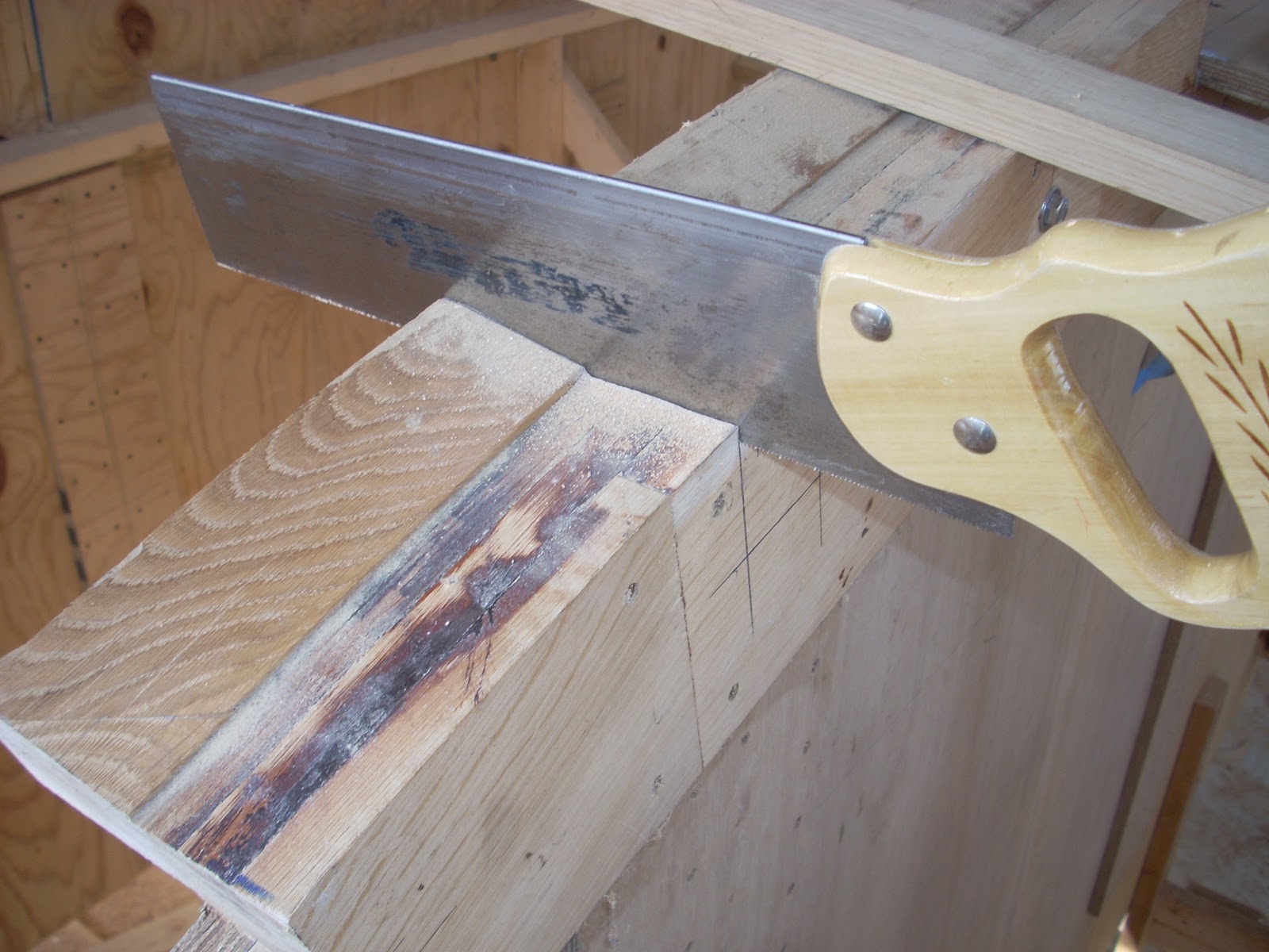
A close up of the blade (turned off).  See the nice even pattern in the layers of the plywood.  This means that I have achieved a nice even scarf joint.


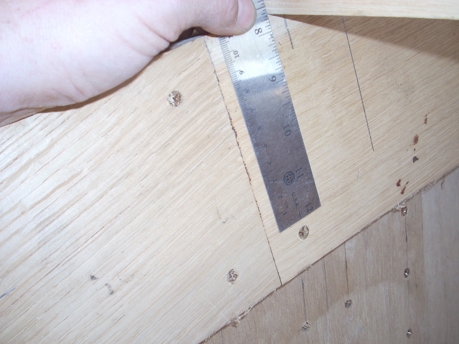
1/4" X 12" X 16' strips of planking.  The scarf joints are held tight with bar clamps while the epoxy cures.
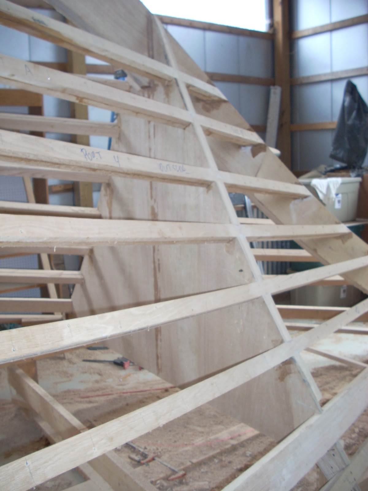
I temporarily placed this first strip on the hull this morning to see how it would go.  The process is going to take a bit of a learning curve not to mention quite a few clamps.  When I was done, I was very pleased with how it laid on the hull.  
July 2,

I've ripped a total of 6 sheets of plywood and cut a scarf on all but the last piece.  This is enough plywood to make 12 16 ft pieces (~200 sqr ft).  On the last piece, a bolt holding the blade guard came out.  While clearing the waste piece, the waste piece jammed the guard into the blade.  This would have been prevented by the bolt which was no longer there.  The guard jammed the blade to a halt slamming the grinder and guard back into my finger.  The finger survived but is cut and bruised.  The cut isn't that deep but the bruising makes it pretty sore.  Ironically, the guard caused the problem and protected me at the same time.  I will have to rebuild the guard.  I'll make the new guard out to 16 gauge steel to avoid the blade from grabbing it in the even of a blade strike.  I also plan to use Loctite threadlocker on the bolts so that they do not vibrate free.  Lesson learned and no loss of fingers.  I'll get some pictures of the old and new guard soon.

Jan 12, 2014 update - actually that finger injury took almost 4 months to heal and I still have residual stiffness in the first joint.  The cut was deep and blunt so I think a lot of damage was done.  I was both lucky and unlucky at the same time.  Be careful out there.
This was the old guard.  It was made our of 16 ga galvanized and spot welded.  It had supports on either side and at the top.  One of the supports vibrated loose and a waste piece pushed the guard into the blade.  You can see on the right where the blade cut through the guard and then at the top where it snagged in the guard kicking it back.
July 4, 2013

Nothing says independence to me like working on the boat.  I've fully repaired and tested the scarf cutting machine.
The new guard made from 20 ga steel continuously welded.   I'm going to add Loctite to the bolts so that they will not vibrate loose.  This guard should take a blade strike without instantly cutting through.  Also, since it is continuously welded it should no snag.
A side view.  

I've also worked on the bonding strips for the boat.  I'll add so considerable text about bonding soon.  For now, the bonding strips are 1" X 1/8" copper strips that run almost the length of the boat on either side of the keel.  Purchasing bar stock would have been very expensive.  I have a friend in the sheet metal business that had some 1/8" sheets and he cut some strip from them at a very nice price (actually less than the per pound price at this time since he'd had the copper laying around for some time).  The only issue is that shearing the copper caused the strips to twist so I had to take the twist out.

a few of the copper bonding strips.  Notice the twist in them.  This occurs during the shearing process.  The shear is like a guillotine and cuts the copper sheet from one side to the other and not all at once.  This tends to twist the metal.  The twist would be barely noticeable with steel but copper is relatively soft.  

So what is bonding anyway?  From Miller/Maloney's book Your Boat's Electrical System, they say there are four reasons to bond your boat:

  1. Bonding provides a low resistance electrical path between otherwise isolated metallic objects, reducing the possibility of electrolytic corrosion due to stray currents between objects.
  2. Bonding prevents the possibility of above-ground electrical potential on exposed metallic cases and parts of electrical equipment should fail should a fault develop in such a device.
  3. Bonding provides a low-resistance path to ground for voltages higher than system potential, as, for example, during a lightning strike.
  4. Bonding minimizes radio interference.
All powered items should have their cases connected to the bonding system including the engine, auxiliary power plant, electrical cabinets, etc.  Zinc blocks and all through hull fittings will also be connected to the bonding system.

July, 7

I've glued some more of the plywood together and cut some more scarf joints.  The new and improved machine actually works better than the last incarnation.  The guard is much more stable and hopefully safer.  I also put in a few more hours of sanding the keel so there is a smooth transition to the hull.

July, sometime

I've managed to straightened these copper strips out and I'll tell you it was not easy.  I'm not sure it was worth the effort but I did save quite a bit of money.

Bonding strips straightened out with flanges bent on the ends.  These are ready to install.


I've installed three of the strips at this point.  Notice the short horizontal boards attached along the seams.  These are temporary blocks attached between the longitudinal battens to hold the plywood strips flush with the hull.  Oh, and that is my wife off to the right encouraging me. 

The first three strips installed and sanded.  I've decided to sand as I go.  Once all the plywood is on, access will be more difficult.
Two more strips installed.


Monday, April 15, 2013

Finishing the Bottom Framing

Well, making all those notches (I have not counted them yet) has been a test of endurance.  I am very happy to tell you that they are all done.  Yes done!  There will be the inevitable tweaking as I fit the longitudinal battens but for the most part I'm finished with them.  It's now time to finish up the framing of the hull.  That means fitting the last longitudinals and finish laying in the keel.

The first lamination of the longitudinal battens are fitted to the starboard side of the hull.  These are ready for epoxy and screws.  
I need to make some pictures of where these longitudinal battens meet the stem.  Not only do they meet at a shallow angle but I had to put considerable twist into them so that the hull stays true.  Very difficult to make.  I estimate that I spent an hour on each of the last two miters meeting the stem.  See below.

You can see two of the tricky miters where the longitudinal battens meet the stem.  The lower one runs through a notch as it meets the stem.  If the shape of the stem and bulkhead were off, this transition would have never worked and I'd be in for a bit of additional work.  Luckily, everything is going as planned.

This is the lowest (top when the boat is upside down) batten and it makes a gradual transition into the step.  That was not an easy cut to make.  The second lamination of the batten should meet flush with the bottom (top in the picture) of the stem.

April 20, 2013

The following are a few shots of the boat as it stands today.  The building is too small to get a really good shot of the whole thing.


Port side of the boat taken from the stern looking forward.
Port side of the boat taken from the bow looking aft.
Port side of the boat showing the longitudinal battens converging on the transom.
This is a fun shot standing on top of the keel (or where the keel will be)  and looking down at the bottom of the stem.  The "C" clamp is placed onto the batten to help make the twist necessary  so that the second batten lamination will be flush with the stem.  I use the leverage the "C" clamp gives me in order to twist the wood.  My batten twister that I made for this purpose won't fit into the space.  Improvisation has been my constant companion especially working alone most of the time.
It's always good to get a little help or better yet two.  The little girl is Sophia, daughter of our good friend Ana and the boy is Isaac, the son of our good friends Michael and Stephanie.
May 6, 2013

All the longitudinal battens are in place where they belong on the hull.  Three need to have their tapers cut where they attach to the stem and another three are ready to permanently install.  It's so nice not to have to craw under 50 foot long battens all the time just to get to the other side of the work shop.

May 16, 2013

The longitudinal battens on the port side are permanently bonded and screwed into place.  The starboard longitudinal tapers are cut and clamped in place waiting to be predrilled for installation.  We are very close to finishing the framing for the hull.  A little faring and laying in the keel laminations and we will be ready for the 'planking' phase.  This will take quite a bit of epoxy so I have ordered a ~50 gallon drum of West System epoxy from West Marine (unrelated) in Nashville.  They should have it by Wednesday about the same time that I'll scrape up enough money to pay for it.  This will be the largest expenditure on the boat in 2 years but it will allow me to advance the construction through the finishing of the hull.  This will represent half (depending on how you look at it) the construction of the boat but only 10-20% of the cost.

--Addendum March 15, 2015

I've been storing the epoxy in the one gallon cans and the hardener in the pint cans so that I can use the measured pumps for metering the parts out as well as the convenience of the easier handling size.  My shop is not heated so the epoxy goes through freeze thaw cycles in the winter.  This tends to crystalize the epoxy and make it thicken considerably.  Heating the epoxy to 120 degrees F. will restore it to its former viscosity.  I warmed my oven to 200 degrees F. and and turned it off.  I then placed the can of epoxy with the cap off but with some foil lightly crimped around the opening in the oven for about 10 - 15 minutes.  I watched it closely because I was concerned that I would stink up the house.  My wife was home and she's got a very sensitive noise.  To my surprise, the process went smoothly with no discernible outgassing.   The epoxy was as good as new.


May 19, 2013

Not much epoxy work going on since the temperature here in Alabama is well into the 80's (27 degrees Celsius).  I only have fast hardener (205) left and not much at that.  I ordered a gallon of slow hardener (206) along with the 50 gallons of West epoxy.  I hope to get up to Nashville on Wednesday to pick it up.  I have not been idle though and have finished the rough faring on the port side of the boat.  She is really starting to look good.  I have also cut out the second lamination of the transom and butt glued it together.

The second lamination of the transom clamped and glued together.   Clamping, except for the one in the front, consists of temporarily screwing one side of the transom to the table and then applying glue to the butt.  Wax paper is laid along the glue joint on the table side in order to prevent gluing the transom to the table.  After glue is applied to the joint, I bring the remaining transom piece into contact with the 'clamped' one and screw them together.  This will make a nice joint that is as flat as my table.
May 23, 2013

The port side of the framing and faring is finished.  There will be some fine tuning before the 'planking' commences.  Today, I'm taking a trailer to Nashville to pick up a 52 gallon drum of West System Epoxy from our friends at West Marine.

The framing for the port side is finished.  Also note that the rough faring of the floor boards and bulkheads are also complete.  I expect some fine tuning of the faring once both sides are finished. 
In the West Marine store East of Nashville standing next to my 52 gallon drum of  West Epoxy.   We loaded it onto my trailer with a forklift and made the 2 hour journey back home.
May 29, 2013

All the longitudinal battens are installed and the bulkheads and floor timbers are shaped to the hull.  Some fine tuning on the faring still needs to be done.  
June 17, 2013

The keel is finally permanently laid in place after installing it temporarily countless times.
The keel laid in place before faring looking aft.

The keel laid in place before faring.  A closeup looking aft.

The keel laid in place before faring looking forward.  Notice the discontinuity between the edges of the keel and the bulkheads.  This will have to be faired to match.  See below.


A closeup of the the stem and keel coming together.  The top of the keel has been faired to match the stem.  Now it will have to be faired to match the bulkheads.  The black line is where material will have to be removed in order to create a fair hull.  The line was determined using the method shown in the following figures.  Copious amounts of epoxy were used with the keel layup to ensure a good bond.  The drips will have to be sanded clean where they will prove unsightly.

This view shows a batten bent over the bulkheads where they meet the step.    The batten shows me where I need to remove material to make the transition smooth.

More of the batten showing me where I need to remove material.

The mostly faired keel now showing a smooth transition between keel and bulkheads.  Some refinements still needs to be performed.
I never attached the temporary sheer clamps to the transom because the jig was in the way.  The sheer clamp is just a longitudinal batten that marks the end of the bulwark.  With the keel installed I can now remove the rear of the jig and install the clamp.  The temporary sheer clamp provides a solid member to attach the hull laminations beyond the deck in order to create the bulwark.  It will be removed after the boat is turned over.  Then the permanent bulwark cap will take its place.

This image shows the positioning of the temporary sheer clamp on the port side of the transom.  I use a short temporary piece of wood to ensure the sheer clamp (last longitudinal) mounts flush with the transom hull lines.  I then screw it in place in such a manner that I will be able to remove it at a later time.
The last 'floor board'  that will be attached to the forward bulkhead to add support to the stem attachment.  It will be bolted to the bulkhead frames and lag bolted through the bulkhead into the stem.  I used a chisel to make the long beveled cuts.  It was really nice to use a chisel in this controlled environment instead of upside down and sideways working on the notches.
Last floor board member installed!  It is bolted to the bulkhead through the sawn frames.  Later I'll add large stainless lag bolts through the floor board into the stem.


One of the things that you need to prepared for when working on a project of this magnitude is tool failure.  If I had to buy a new tool every time one broke I would not be able to afford to work on the boat.  First of all buy the best tools you can afford (not the most expensive).  The best tools are those that do only one thing.  I do not believe in multi-tools they tend to do a lot of things poorly and are generally not made well.  When a tool fails be creative about fixing it.

The right item is the original tension release for a sanding belt on a belt sander.  It is made of plastic and was doomed to fail.  The right item is a newly fabricated replacement that I made out of some spare aluminum.  It works better than the original.


The new tension release lever installed in the belt sander.  Just above the handle you can see a switched that I installed to replace the failed trigger switch (~$80).  It has two settings:  constant pressure forward operation or permanent on in the rear position.  I just happen to have this switch laying around.  You need to be careful that the switch is not pulled back before you turn it on or the sander will run away.  

Sunday, January 13, 2013

The Keel

Keel

The keel is the backbone of any boat or ship.  In traditional boat building it's the main structural element in which frames are attached.  It' also one of the first things built with everything else built around the keel.  The boat I'm building is not a traditional build boat but rather it's a hybrid.  In my case the keel is laid into the bulkhead after the hull already has its shape.  You've seen the keel temporarily installed in previous posts but now I'm ready to make it a permanent part of the boat especially since the temperature will finally be warm enough to actually use epoxy.  The temperature needs to stay above 60 degrees for at least 24 hours in order for epoxy to cure properly.  

Not so fast unfortunately.  I mentioned in an earlier post that the floor timbers continued to shrink after I had notched them for the keel (I had to take them all down and re-plane them before I installed them onto the bulkheads).  This forced me to raise (make the notches deeper) the keel around 3/16".  This should not pose and issues because a filler strake is used to bring the keel flush with the bottom of the hull after the hull planking is installed.  In a few instances I needed to lay in shims to bring the notches in the floor timbers down to the right level.  All of the notches in the floor timbers needed to be have at least minor adjustments.  

This figure shows thin laminations being glued into the bottom of the notches in order to maintain fairness of the keel. Three of the large floor timbers needed these laminations.  All required minor adjustments.
All the floor timbers back in place and ready for the keel.

Before I get to the keel, I used my shim making skills to fix a few other issues.  One of the longitudinal battens that terminated into the step was slightly recessed.  This was only apparent when I started to fare the bow by using thin battens bent onto the longitudinals.  I laminated a thin layer onto the batten and later I'll sand it down to shape.

Laminated a thin shim onto this longitudinal batten.  A short 1" X 2" board is used to apply even pressure to the shim to ensure that it is evenly bonded.  Wax paper is used to ensure that the clamping board can be removed after the repair is finished.

I decided to fix another issue while the temperature is nice.  A small 14 inch section of the third layer of the shear clamp became delaminated.  It's part of the shear clamp that was significantly shaped at the bow.  I clamped a piece of wood below the shear clamp where the repair was to be made so that the epoxy would not leak out of the bottom of the repair.  The separation in the shear clamp was filled with epoxy.  I then clamped the shear clamp tightly to ensure that the epoxy would be squeezed evenly throughout the delaminated section.  This is when I was reminded of what a liability cheap tools really are.  I figured 'C' clamps from Harbor Freight would work well enough.  I'd already bent a few but I had not broken one until now.  It's frustrating when your performing a critical task and your tools fail you.  The problem is that I need a very large number of 'C' clamps for this project and I figured I could get cheap ones.  There simple in function and made out of steal.  Actually, now I know they're cheap cast iron.  For the most part they have served their propose though.  I would recommend having a large number of cheap 'C' clamps for light clamping and a few good ones in critical situations.

Cheap 'C' clamps might not be worth the price.  I actually broke this 'C' clamp with hand pressure only.
The delamination of the shear clamp being fixed.  It looks complicated but it worked perfectly.
 Back to the repair. The repair looks awfully convoluted in the figure above but I was very pleased with the results.

After letting the epoxy set up overnight, I'm almost ready to install the first section of the keel.  A little sanding of repairs and I dry laid the first piece in place starting at the stern.  Drilled for the #10 2" silicon bronze screws and mixed up some epoxy.  I'll need a thickening agent for the epoxy so it will better fill small gaps.  The West epoxy, in its natural state, is very viscous and will run off a surface thats not flat.  There are various additives such as silica and micro spheres that thicken the epoxy and make it a better bonding agent.  I have just enough to make one batch of epoxy.  It turns out that I'm almost out of screws as well.  100 of these screws are $60 and the filler is around $30 but I'll have to order both from Jamestown Distributers.  I did, however, get that first piece (16 ft) installed.

Sunday, January 6, 2013

Buenas Notches

Many many notches later I finally finished the notches up to where the floor timbers start and then I ran out of wood for the longitudinal battens.  I would have  to save up some money which was getting a bit more difficult now that I have a new room mate (whom I married on October 7, 2012).  Nevertheless, I was able find enough money to get 500 board feet of lumber from Davie Ashley Sawmill in Elora, Tn. 

Stopping in Elora Tennessee for a quick drink after buying another load of white oak at Davie Ashley Sawmill.  This 16' trailer has paid for itself over and over again.  To the guy who literally took the next to the last corn dog out from under us at this convenience store (not pictured), you might want to avoid my wife for a while.  We actually ordered two corn dogs from one person behind the counter to have the guy behind us (yes he heard) order one from someone else who was quicker to the draw.  What is this world coming to when corn dogs and respect are in short supply.
I have at least one batten installed in all the notches up to the floor timbers.   You can see all the new battens that I made from the new load of wood waiting on the table in the foreground.
With this new load of wood I've changed the method of how I make the longitudinal battens.  Before I cut the wood to be as straight as possible and glued the battens together to be as straight as possible.  Now I'm ripping the lumber and following the natural curve of the wood.  The finished battens are then sorted by shape (straight, slight curve, radical curve, etc.)  I then select battens to fit the actual curves on the boat.  This has resulted in less waste and a much easier time fitting the battens into place at the cost of a little more time sorting and selecting the pieces.  I also gain increased strength since now the grain always carries true the entire length of the batten.  Before, I glued as manny battens as I could together.  Now, I can only glue up a few at a time and I've got to label and keep track of them.  I think its worth it though. There is less fighting to install them and I'm sure less internal stress in the final assembly.

The longitudinal battens finished up to the floor boards.  I've even faired the bulkhead to the hull contour in this photo.  Notice how the longitudinals flow smoothly into the stem.  This is no accident.
Back to the notches.  I've put together a series of photos that explains this grueling process.
After measuring for the approximate placement of the battens (they should be as evenly spaced as possible), a long batten is clamped in place.  There is a trade-off between the best placement of the batten and the natural tendency for how the wood bends.  This was more of an issue during the more radical transitions between the barrel shape of the mid-hull region and the bow.  The gentle curves near the keel seem to follow a natural bend for the wood which means I laid the hull out in a smart fashion or more likely I got lucky.
Clamping the batten in place on top of the bulkhead frame.  This bulkhead also has a 3" floor timber bonded to it.

It's important that the batten is clamped so that it lies flat against the bulkhead.  Of course it can only lie flat on one edge of the bulkhead because the edge is square and the batten does not fall normal to the bulkhead.  I had to be careful not to over clamp the battens because I need to measure the angle between the batten and bulkhead.


I use a square to project where the notch sides should be drawn.   Even this is not straight forward because the square will not lay flat against the frame and sit flush on the batten at the same time.

With the batten sitting naturally on top of the frame I measure the distance between the lowest part of the frame and the bottom of the batten.  This measurement plus two inches is what I will use for the depth of the notch from the bottom of the batten on both sides of the bulkhead.  Since the batten is at an angle to the bulkhead the final depth of the notch will actually be a little more (note the angle the rule makes to the batten and that the width measured at this angle is larger than the one inch thickness of the batten).  But this will get me close and I'll take the final measurements after I fit an actual batten into the notches.  


Marking the depth of the notch.

Notch drawn on the frame.

I've moved the clamp to the other side to mark this side.  The clamps often get in the way of marking the notches.

I start the cut for the sides of the notch with a hand saw.  I then use a Sawzall to cut most of the remaining side of the the notch.  I then finish with the hand saw.  I originally used the hand saw exclusively but I kept hitting screws hidden in the frames and after ruining 4 or 5 saws I switched to the Sawzall.  Ironically, the Sawzall is not really much faster than a sharp hand saw but the 4" floor timbers and frame combination is way too much for these short mitre saws and there is just no room for a long saw and once you hit a screw your done with that saw. 

The net step is to slice up the notches with a skill saw.  The skill saw is set to about 1 3/4" depth and I make 1/4" - 1/2" slices out of the notches.

A closeup of the slicing.

Some rough chisel work and the bulk of the material is cleared from the notches.

Notch cleared of the bulk of the material.

Using a hand saw, I make of cut in the center of the notch down to my depth lines on both sides of the frame.  I then can use a chisel and finish the notch.  Once a run of notches is cleaned out with the chisel I lay a temporary batten in place.  I note the places where it's too high and where the notch has the wrong angle.  Remember, I purposely designed the notches to be too high.  Now is where I measure the correct depth of the notches.  I also check to make sure the notches are not too tight.  A firm push or light hammer work should bring the batten flush to the bottom of the notch.  The most work is when the notches are too tight and I have to widen them.  This is painful chisel work especially where there are floor timbers.
A finished run of notches.  I hope there is not an air vent 2 meters wide at the end of this trench because my defenses are built around a large scale attack.
13/02/02
This is my nephew Joshua learning how to make the notches.  It sure is nice to get help occasionally.  This is the last run of notches on the starboard side.  My goal is to have the hull ready for "planking" this spring.
13/02/10

Finally finished all the notches on the starboard side of the hull.  I have 3 more runs of notches on the port side to go.  The last two runs notch through all the floor timbers and these take about two days worth of work to get right.  It's also difficult to work on the bottom of the hull.  There are few places to keep tools.  Floor timbers are close together which makes working difficult.  Also it's like working on top of a jungle gym with nothing but sharp edges.  Well, I'll be glad when the last three runs are complete.  Tonight I'm exhausted.     
13/02/17

I'll add a picture soon.  I've started the final three runs of notches on the port side.  I didn't get too far this weekend because it was the weekend that I started the vegetable garden.  The garden is tilled, marked, fenced against rabbits, and the cabbage and lettuce has been planted.  All the other plants have been started inside.  Next weekend I'm going to try my hand at snow boarding so there won't be any progress for a few weeks.  Wish me luck.

13/04/02

Okay, so no snow boarding in 45 degree weather while it's raining.  Progress on the boat has be relatively slow but has not stopped.  Almost done with all the notches.

A close up of the work on the notches on the port side of the hull.

All the notches are roughed out and most are clean.  I have not laid in the longitudinal battens to check alignment or depth.  That is the next step.