Monday, May 4, 2020

May 2020

May 3,

Working on the bow framing that will support the deck and general structure of the bow.  The strongback down the center is a 2 inch (5 cm) by 6 inch (15 cm) member made up of two layers of 1 inch (2.5 cm) by 6 inch white oak.  The bowsprit (6 in x 6 in) will match the strongback width and extend over the bow a good ways.  

The strongback notched into the forward bulkhead with a pocket notch in the near horizontal deck beam.

A close up of the horizontal deck beam showing the detail on the exposed bottom of the beam.  This detail will continue for all the horizontal deck beams and deck house roof beams.

A close up of the pocket where the strongback connects to the deck beam.  The strongback will have to have the slight curvature of the deck.  I'll use the belt sander for that later.

This is how the strongback mortises into the stem in the bow.  The bulwark at the tip of the bow will be cut out to accommodate the 6 x 6 inch bowsprit.  It's a little messy up there right now but all that will be cut out and cleaned up later.  
May 10,

Happy mother's day to all the mothers out there.  This son worked on his child over the weekend.
These pockets can be made with a router.  There is enough room for the guide.  I've made two of these guides, one for 3 and one for 6 inch pockets.  I make three passes with the router to get the 1 inch (2..5 cm) depth I need.

The router leaves a bit of a curved corner...  

...which can be cleaned up quickly with a chisel,


This pocket must be cut by hand.  There is no room for a router.  Unfortunately, this is  the situation with most of the pockets on this boat.  I start with marking the outlines of the pocket and then making the diagonal cuts about a centimeter apart.  I can even hand cut the tapper which is not done here but I did do that on the second one I made.  Luckily, my technique and skills improve with every task.

Now I just rough cut out those triangle with a chisel.  It looks ugly right now.

I carefully chisel along my lines taking out a little at a time.

Finally, the pocket is complete.


The entire set of pockets and notches for the framing member.  The notch is started with cutting the sides partly with a hand saw.  Finishing to almost full depth with the SawZall (reciprocating inline saw).  I then use a skill saw to rough cut the middle.  Then it's all chisel work.  I leave it a bit shallow until I check the fit to get the bevel correct on the bottom.


I've dry laid them in for now.  I'll glue and screw them all in at once.  Time for the left side.
May 17,

And now the other side:

It looks fairly nice.  Next, I'll need to drill the holes for the screw.  

All epoxied in.  This proved to be very messy.  I had to stand in between those members in order to be able to drive the big screws.  I got epoxy everywhere but mostly on myself.  I've since sanded all that nasty epoxy away (not on me but the boards) and taken off the 'squareness' of those board so they don't interfere with the fairness of the deck. 

Friday, April 17, 2020

April 2020

April 17,

Still working on laminating beams for the deck house roof.  I've made 5 so far which is about half of what I need for the aft section.  A little more for the forward section, but those will be shorter but using the same form so the curve is identical.  I'm out of 10 ft lumber so I'll have to start on the shorter ones.  Definitely will need some more white oak very soon.

Here are the five deck house beams stacked on top of each other.  They are identical and match the pattern exactly even though I put a little more bend in them than necessary.  There is always a little spring back that you have to take into consideration.


This is the pattern for a laminated knee to hold up the carlings for the deck adjacent to the deck house.  I decided to steam bend and laminate white oak instead of a plain plywood knuckle.  You can see the outline of the piece I wish to make in pencil.  


This is the first attempt at bending the knee.  I had to add some modifications to suit the task.   They were suitable but the second attempt went much smoother.  Notice that I added two more blocks for clamps at the end.  I also drove a few drywall screws through the plywood and into the table so I could better man-handle the strips.  I've broken one piece each time I try to bend a group.  From what I gather this is fairly normal.  Expect some broken pieces unless you want to go very thin on the strips.  You can see one of the broken pieces in the image just to the left of the red squeeze clamp.  It is still clamped to the work with the "C" clamp in the upper left of the figure.
April 28,

This is the partially made piece.  I still need to make it a hair thicker and add some material on the outside of the bend .  It did not turn out too bad.  

This laminated beam supports the deck where the deck house terminates in the bow.  There is a strongback that will be notched into the center of the beam and the bulkhead near the bottom of the image. The strongback will continue until it attaches to the tip of the stem.  The laminated beam will be notched so the top of the beam will be flush with the bottom of the deck.  Once the deck is installed, the bowsprit will lay on top of the deck and strongback held in place by two vertical members forward of the last bulkhead (bottom of the image).  This will make a strong triangle: Stem, bowsprit and strongback, and vertical members mounted forward the bulkhead.  

Just cut the joinery for that forward laminated deck beam. The next one is behind it upside down.

A close up of the fit for this deck beam.  It is a little high in the rear to account for the slope of the deck.  I'll sand it smooth with the deck structure when I install it.  I still have to notch out for the strongback going down the center.

Here is that laminated beam that was upside down in the previous photo.  This is the type of joinery that is needed on the ends.  It required a little adjustment before it fit snug.
The laminated beam that is not adjacent to a bulkhead took a little extra work.  I've been measuring along the curved top for reference lines to cut the ends of the beams.  What I did here was install a fake bulkhead (well just the top part) with the correct curvature and used that to work out the reference lines.   When I install the deck house beams I'll have to do something similar.  I'll make my fake bulkhead for the longest one and trim it as I move toward the shorter ones.
Here they both are.  They are just clamped in place right now.  Actually that one in front just fits tight enough that it wont move.  A mallet blow to each end sets it pretty good.  Again, I'll have to notch out for the strongback and a few other members that support the deck later.


I hope all of you out there are staying safe.  We're screwing this thing up in the old USA.


Monday, March 2, 2020

March 2020

March 2,

We did a lot of work over the weekend.  A lot of the rough cabinetry has been marked on the bulkheads including the deck and cabin outlines.  All the passageways have been cut.  I left a a good bit over some of them so I can retain reference lines and mark the deck house outline.  I'll cut them out later.
On the left starting in the foreground of the picture and moving toward the bow:  Hanging locker with shelf on top. Shower with head besides, V-berth stateroom with lavatory to the left.  V-berth forward. 

The passage on the right will be the companion way leading to the V-berth door.  On the left will be doors into the shower and on to the head.  The picture is being taken in the area which will contain the port and starboard cabins. 

What a convenient place for the plans.   This is the doorway leading from the salon to the main cabins.

Your not going to wipe the smile off our faces anytime soon. 


And time for something a little different.  I've got a great but difficult plan for the cabinetry which will require a bit of steam bending.  Actually, there will also be a lot of interior trim that I may use the laminated steam bending technique.  I have steam bent oak before.  I hooked up a 4" PVC schedule 40 pipe to a kettle and did it in my kitchen.  I'm married now so that is out.   Besides PVC kinda droops and melts over time so I wanted something a bit more durable.  My solution is to use 4" metal down spout that I have laying around.  I drilled holes in the side and placed short pieces of threaded rod below the centerline to keep the steamed wood in the center of the tube.  I make two wooden end caps, one tapered to be removed on the right the other with a hole in which I threaded some galvanized pipe I had laying around.  The pipe was attached to a chrome shower head pipe which was roughly threaded into the lid of a durable cooking pot.  Made a stand out of wood and bought a one eye burner from Walmart for $12.   That was the only item I purchased.  Put water in the kettle, oak strips in the tube and turned the burner on.  About 45 minutes later I had beautifully steamed oak strips.  There was just one issue.  Water was able to leak out the end but as the end cap soaked the steam up and swelled, the water became trapped and the wooden end cap was very difficult to remove.  So I'll drill a small weep hole in the bottom of the tube right before the end cap and I'll put the end cap in much looser than before.   

Completed steamer. 

This is one of the cabin roof beams dry laid before glueing.   I cut up some steel angle iron for clamping.  I took the pattern and transferred it to the table.  Added some 2x4 stock under the table top so the lag bolts would have something substantial to grab onto.  I then lag bolted the cut angle iron along the pattern.  I used 1", 11/4" and 3/4" width boards.  The 3/4" board is actually quarter sawn so it is on the inside where that gorgeous flecking will show.  These boards are cold molded so no steam is required.  

Same piece but this time I used epoxy.  I laid some plastic down to keep the piece from sticking to the table.  A lot of clamps were required to close the gaps.  

This is the bulkhead that will have the beam attached to along the top.   I've placed it above so it is ready to measure and fit  into place.  I'll have to be very careful fitting the beam, nothing is square on a boat and the ends will have to be notched around the triple shear clamp.  There is actually a bit more curvature than what it looked like when the bean was on the table.
March 32

So, I learned something that I'd like to carry on to my readers.  I've made two of these laminated beams that are 2"x4" actual width.  They are made up of 4 1"x2" pieces of wood.  After glueing up in a form and letting them cure overnight, I get 3/8" of spring back.  The one that bolts up against the bulkhead was easy to fix.  I made it slightly longer and used a clamp to reintroduce a little more bend.    Then I trimmed one of the joints at the end until  I had a near perfect fit.  You can see me fitting one of the ends in the figure below.  The second one I made, I got the same spring back but this one is going to be free standing between the deck carlings.  I'm going to have to rig up something to get that little bit of bend back.

I'm fitting the end of the laminated beam into the shear clamp (that ruler is sitting on the shear clamp).  There is about 1 1/4" that fits under the shear clamp.  If you look close there is still a small gap between the laminated beam and the shear clamp on the right.  This is because that 1 1/4" that fits under the shear clamp is about 1/32" too long.  I took it out and trimmed it up.

A real sweet fit.  The only issue was that the bend relaxed a bit and I had to use a clamp in the middle to pull it back up.  Once the beam is fit, the sides of the boat hold the beam to shape and there is no need for the clamp in the center.

The is the second laminated beam that will fit 18 inches in front of the one just made.  It will not span the entire width of the boat but fit between the deck carling that supports the deck inboard where the deck house rises.  
I've also started on building the laminated roof beams of the deck cabin.  These are slightly smaller, 2"x3" and not as long.  I'm going to try to take that 3/8" into consideration when I build the form.  Maybe a little less than 3/8" since the individual pieces are 3/4" instead of 1" so I expect less spring back because it should take less pressure to form the curve if the curve is similar.  Something else to take into consideration.

That 3/8" really did the trick.  So I made the jig deeper by 3/8" and used a stiff board to make a smooth curve to the original marks on the ends.  Laminated the four boards up and let cure overnight.   I released the beam from the jig and it sprung back right on the original contour line.  I've made two thus far and they both came out very nice.

Wednesday, February 5, 2020

February 2020

February 5

I've been slowly rigging the hull so the roll-over will go as smooth as possible.  I've finally scheduled it for Sunday February 16.  Come on by if your in the Huntsville Alabama area and help or spectate.

You can see the chain hoist attached to the wall in the center far left of the image.  This is one of two  chain hoists that will slowly roll the boat over.  There will be two more on the opposite side preventing uncontrolled roll and two more at the pivot point to prevent the pivot point from moving or scooting along the floor.  The two at the pivot point will also be used to slide the entire rig to over mid roll so that we keep the hull to the side of the building.  There will be sheet metal skip plates and grease to ease the sliding.  
The attachment point to the post is a compromise.  I want it as low as possible to reduce the stress on the post but high enough so that most of the force on the hull goes into a rolling moment.  I figure just short of horizontal at the start will work fine.  Once the boat starts rolling, the rig will pass through the horizontal (or maximum efficiency) point about when gravity will start lending a hand.

I've already cranked the chain hoist so that the entire weight of the boat is almost on the pivot point.  It took about all that two ton chain hoist and that 6"x6" post could take.  Luckily when we actually roll the hull over there will be two rigs rolling the boat.  This gives me about a 100% safety margin by my estimation.

BOAT HULL FLIP WAS SUCCESSFUL.  Pictures coming soon... actually I did not have time to take a single one myself.  Ive got friends though and boy did they turn out for the day.

Here is a taste:


I learned a lot during this maneuver.  It took a minimum of 6 chain hoists with a minimum capacity of 2200 pounds (1000 Kilograms).  We also had three more come-alongs that proved convenient.  Sheet metal was laid down as tracks for the wooden rollers and the wooden rollers were liberally greased to allow easy sliding.  This turned out to be critical.  We always had control using chain hoists on one side to pull while using chain hoists on the other side to release.  We also always had chain hoists controlling the pivot point on the ground.

After the half way point, the pivot point control had to be switched to the other side while we used the come-alongs to slide the hull over opposite the pivot control.  I used 1/2 inch (12.7mm) eye bolts for all attachment points and most importantly, I welded the eyebolts closed so they would not open under stress.  This is critical.  Either use eye bolts that are factory welded or weld them yourself.  If not they will pull open.  We always had two chains for redundancy and to make things easier.  You will need a spare come-along or chain hoist to relieve tension on the chain when re-rigging.  At no point did we have a single chain taking weight.  Although it was not the chain that concerned me but the point of attachment.  There is a lot of stress on those points especially when the chains are at steep angles to the eye bolt.

It is also a good idea to have spare 5/16" quick links for adjusting the rigging.   Make sure all your chain and hardware exceeds your chain hoist capacity by a good margin.  There were times where we were actually pulling against each other putting huge stress on the hardware (and hull).  We learned quickly to recognize these situations and avoid them.  Avoid shock loading.  I used rubber bungees on the chains as a snuffer for the side that was releasing so that when they took the load, the bungees would absorb the shock.  I discarded them on the re-rig (when switching sides) after I determined that going slow was good enough and the bungees caused some difficulty when trying to re-rig.  This maneuver took 4 hours and required 6 people to complete.

Feb 26.

I've started marking lines on the bulkheads.  Lines to cut (actually cut one) and lines where attachments will be made for the interior.  Mostly, I'm looking forward to having a passageway along the interior so I don't have to climb over the bulkheads to get from one end of the boat to the other.  I've also cleaned up the shear but have not removed the temporary shear clamp yet.

Tuesday, December 3, 2019

December 2019

December 3

Well, I finally finished up the hull and all that sanding.  I went over it pretty well and filled all the little pin holes and dimples.  I'm sure I missed one but I'll find those before the paint goes on.  Right now it's time to prepare to flip hull over and start working on the inside.  To that end, I've removed all the scaffolding that will be in the way leaving just 30 feet on the wall side to attach pulleys and have people stationed for the flip.

Flipping the hull is a bit of a misnomer.  I'm actually building a jig so that I can roll the hull over until it is right.  I will use six 2 ton chain hoist.  Two to roll the hull over and they will initially be attached to the keel and two of the 6x6 posts.  Two also attached to the keel but pulling the opposite way to prevent the hull from rolling back (I might get away with using one ton hoists here).  Two attached to the pivot point on the ground to ensure the boat rolls instead of scoots.

A nice view from a ladder near the shop corner.  That's Fig in the door way.  He likes to help.

The hull looks even larger when not wrapped in scaffolding.
The first thing was to get a roundish outline to build the rollers.

Adding 2x10s to follow the outline.  This probably would have been easier to use an octagon but the round roller has fewer stress points and easier balancing points to take a break.


I took the aft one down and made an identical one for the front.  I had to customize it a little  to fit properly.   The trick was to make them identical.  Now it's time to layer on the wood for strength.

Making progress.

Essentially we have two layers of 2" lumber with 3/4" plywood sandwiched in between.  I've maintained contact with the hull as much as possible in at least the plywood and one layer of 2" lumber.  All of the joints will be through bolted together.  It will be bolted to the gunwale, building jig frame and into the keel.     

I almost forgot I needed to install the skeg keel stump.  This is the first of 5 or so pieces that make up the skeg keel.  The rudder will attach here as well as the prop shaft.  I need to install this before flipping the hull to ensure that I get the bolt holes drilled correctly.  I shaped the face that attaches to the hull a bit so that there was only a small gap.  I used two layers of woven glass between to make up the small gaps.  One thing I did a little different is that I used thickened epoxy (pea-nut butter consistency) just inside the edge of where the keel stump mates with the hull.  This held the glass in place and acted like a dam for the un-thickened epoxy.  I used temporary bolts to create pressure to squeeze out all the air and used aluminum tape around the seam so that the epoxy would not seep out.


It was very important to make sure that the skeg keel is perfectly in line with the hull.  I also used a sensitive bubble level to ensure that the skeg was not tilted to one side.  I tightened the bolts a little one after the other ensuring that I brought the skeg back to level each time.
 After the epoxy became tacky, I removed the tape and used thickened epoxy to make a fillet around the seam.
The fillet looks a little rough but it won't take much to clean up.  Having the seam a little tacky really made filleting the joint difficult but now I'll have a chemical bond between the epoxy and fillet joint.  I also had a little glass sticking out of the joint which ended up in the fillet.  That just means more strength.  

Tuesday, October 8, 2019

October 2019

October 6

We had a fabulous work day today.  A whole bunch of folks came out to roll on more epoxy, drink beer, eat and be merry.  We worked hard though and managed to get 3 pretty nice coats on... the final three.

We rolled on a nice coat of un-thickened epoxy first thing in the morning.  After lunch we mixed a heaping half cup of West System 422 barrier coat to 600 grams of epoxy and then added 120 grams of hardener.  The 422 thickened up the epoxy quite a bit so the next two layers are a bit thicker.  We also had a bit of trouble keeping the epoxy from setting up in our roller pans.  I think the 422 additive changed the thermal properties of the epoxy in the pot.  We went through quite a few roller pans having to throw out the ones that started to cure up.  Instead of heating up and smoothly transitioning into a hard state, the epoxy took on a texture that seemed like a bunch of spiderwebs were mixed into our pans.  Adding more epoxy early stopped the reaction but only temporarily so we were forced to throw out the roller pans when this started to happen.

For the most part, the finish looks great with just a hint of orange peal.
A close up of some of the worse orange peal.  The swirls above are from the 1/4 sheet palm sander.  Most of the hull is much smoother.  This is from the side that we did when we were tired and had difficulty controlling the cure time. 
This is fairly normal and just means that the texture of the surface takes on the appearance of the peal of an orange.  Sanding with 60 grit on an orbital sander quickly gets the finish smooth and then I'm following up with 80 grit.  80 grit alone is sufficient but it goes quicker with a light 60 grit sanding followed up with 80 grit.  Remember that the 422 additive makes the epoxy more abrasion resistant i.e. sanding will be more difficult.

I noticed one spot, about the size of a lap top, that was missed with the third coat.  I plan to lightly sand and re-role that area and any more that I find.  We were pretty tired by the third coat.

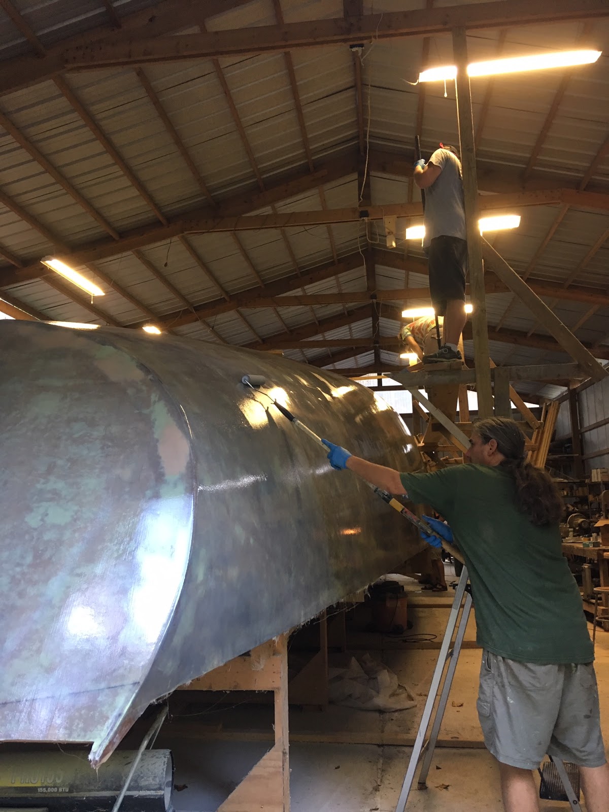
A view of the bow with just a single coat of plain epoxy. 

I found other issues like the bow section in the image above.  We had a lot of goopy epoxy that was starting to firm up on this section.  Basically some shallow lumps.  I got out my 5" orbital with used 60 grit paper and it did a wonderful job smoothing it right out.  Followed by a quick sanding with the palm sander with 60 grit ensured I got a fare surface.  Because there was some thickening in the epoxy, the final layer was thicker and could take a little extra sanding.  The results were better than I expected and there is no reason to re-roll this are.


It felt pretty good to be finished with the day.  That is my wife Laura on my right.  She is always helpful.

October 10,

After scrubbing down the hull with soap and water, sanding commenced.  It really seems to be a chore to wash this hull down.  I've done it many times by now and I suspect I'm going to keep disliking that job.  When it is finished, maybe I can get my wife to take over, she even likes washing cars.  The figure below shows the sanding on the side and bottom aft of the hull.  I started with 60 grit on a small 1/4 sheet orbital sander.  It works pretty well at getting the finish smooth as you can see in the picture.  I've already sanded to 80 grit near the transom.  I'll probably go over it all lightly with 100 grit before I'm done.
October 14,

I've almost completed the initial sanding of this side (above picture) of the hull.  It looks great.  There are a few small places that are going to require touch up but that's normal.  There is another area on the bottom of the other side about the size of a writing desk that seemed to not get the tip treatment.  I've lightly sanded that down and will re-roll with the other small areas.  Careful inspection of the other side did not reveal any issues at all.  I think that side will sand down much easier.  We were much fresher on that side and the temperature was cooler.  I may have pushed my help just a little bit too much but they are great people and the results will be fabulous.

October 16,

Still sanding... and sanding.  It is pretty hard work.  Not as difficult as using the belt sander and without all the fiberglass itching issues.  I should never see the glass again but I still have to put some muscle into the palm sander.  I have a 5 inch orbital that I've use (see above) in a few places where the epoxy got applied poorly and thickly but that tool is hard to hold and you need to keep it moving. It also might take off too much epoxy so I'm happy with the steady but slow progress of the palm sanders.

October 21,

I made quite a bit of progress over the weekend.  I still have a bit to do but I think in another week or two, I'll be ready to start building the structure to roll the boat.  This is an exciting and frustrating point.  I've always said that you take the building process one step at a time but when you're this close to completing a major step, your mind naturally wanders to the next step.  In some ways that's good because it is necessary to fully realize your next step before you take it.  In other ways it's bad because it makes you anxious to be through and that can make you rush critical work.  At these times you just have to take a deep breath and step back and find that Zen of working in the moment.

October 28,

I got through the rough sanding over the weekend.  I also recoated the few areas that needed it.  The epoxy with the barrier coat additive was very hard to roll.  It was 60 degrees F (15.5 degrees C) and I was using the fast hardener.  I think the temperature was the issue.  It was like rolling molasses.  This was fine for the one large area but it quickly became apparent that I should be using a brush on the smaller areas.  This worked much better.  I just had to follow up a few time to take care of the vertical areas where the epoxy had a tendency to slump when spread too thick.  I just lightly brushed the slumped parts back to where they belong with a near dry brush.  This remove some thickness as well as fixed the issue.  Once the epoxy became tacky it will stay were it belongs.

I've also been talking about using the orbital sander almost exclusively for finish sanding and with the filler.  I would have liked to use a long board sander for the filler but I just don't have a set up for that.  The long board would help reduce subtle ripples that I can still feel occasionally along the hull.  I think I'm going to have to live with them.  Once I put the first coat of primer/paint on the hull, I'll address anything that stands out.  I really think the hull is going to look great regardless.  The long board sanders are an expensive setup requiring a commercial grade air compressor for continuous operation.  If you've got the equipment use it during the fairing phase.  Otherwise the orbitals work pretty well.

The next steps will include a wash down with soap again to remove the blush and reveal any more pits and dips that need filling.  Sand down the new epoxy with 60 grit using the orbital sander.  transition to 80 and then 100 grit for the final finish.