September 1,
And the progress continues. I've actually had a very difficult time sourcing seasoned white oak. The saw mills are only selling green white oak if any at all. I'm not sure what is going on but I've had sawmills tell me that they don't sell kiln dried white oak when I have receipts for kiln dried white oak from them. They would not let me even talk to the Peanut who I've done business with before. So much for my favorite sawmill in Elora Tn. Luckily I have a acquaintance who owns a professional tree service company, Lee Haymes, who has seasoned white oak at a very good price. I'm buying 300 bf this weekend and I'll let you know what it looks like.
 |
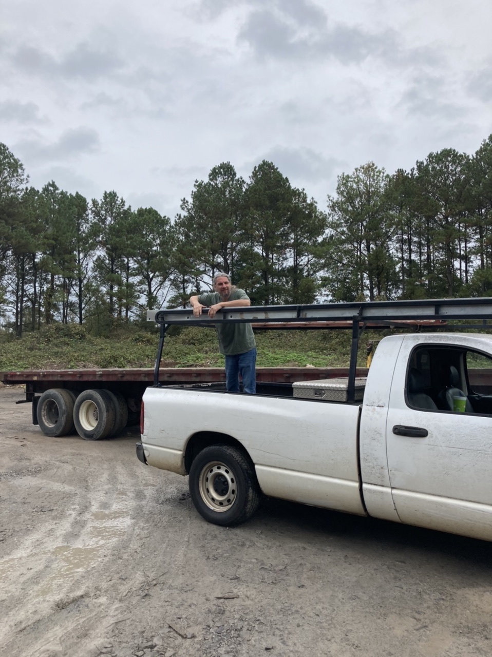
| My new stash of white oak. The pieces in front are 12 footers. The rest are 9 footers that are somewhat quarter sawn. There are 14" wide boards there. The checking of the 12 footers is due to the lack of any sealant on the ends. Always paint or seal the ends of green wood before you rick for drying. I'll still get 10-11 ft board out of these though. This is around 300 bf. |
I've temporarily fit the first layer (actually it is the last layer going from bottom to top but the wides layer needs to be fit first) of the inner carling. It will be three layers of 1x3" tapered to the deck house side cant. I also wanted to make sure I could bend those pieces. If I can bend the widest one, I can bend the rest.
 |
| Here is the only bulkhead (Actually upon further inspection there is one more that required such treatment. It was hidden.) that does not go far enough up to meet the sheer clamp. This is in the settee so we will use the 3/4" gusset matched to the 5/4" white oak short beam. You can see where the pencil lines are where I will cut it out to receive the three laminations of carling. I might replace that plywood gusset with a laminated steam bent piece later. I made one and it's in a previous post. I'm not sure yet but my options are open until I glue it. |
 |
| Here is the carling running along the side of the future deck house. The space between the sheer clamp and the carling is the walking space along the deck. It really is pretty narrow (16" aft) but widens up considerably forward (24"). |
 |
Another view showing the fairly tight radius this piece must be made to make. I'm glad I used the bent wood to my advantage. It really is a tough bend.
|
 |
| I needed to make 12 of these short beams that go between the sheer clamp and the deck house carling. I figured they wouldn't really take that long. I ended up spending an average of an hour a piece on these. They all had to be custom fit and there were a lot of compound angles. You can see quite a few reference lines drawn in pencil. The "x" is the piece that will be removed. I've clamped a piece of straight plywood to act a fence for the circular saw as I cut the bevels. |
 |
| I finish the cut with a hand saw. |
 |
| Is this enough angles for you. What's worse is that the bevel on all three cuts is different. |
 |
| I messed one up. I cut the bevel at the top the wrong way even though I put reference lines everywhere. Which one is cut wrong? Check out the pencil marks. By the way, remaking this one piece only took 15 minutes since I already had all the measurements. The new one fit like a glove. |
 |
| The inner deck house carling's top piece (there are three) will go through this beam and mortise into the one behind while the bottom two will fit into the pocket. I was very pleased with this bit of chisel work. |
 |
| The other end of the carling where it ends in a forward beam. I only made a 3/8" mortise for the first two layers to preserve the integrity of the beam. |
 |
| I'm working on notching them all to accept the three layers of carling. The top layer is shown set to one side for now. |
On labor day, I labored. I'm now ready to start installing the laminated port carling and I have the beam mortised on the starboard side. I'm going to put that together during the week in my spare time. This is about as far as I'm going to go before starting the interior in earnest. I'm sourcing the 17 foot long 5" wide steel "H" beam that the ballast keel will bolt to. It will also act as the main mast step. Once installed, I can start working out the flooring.
September 11,
I did not document fitting the first layer mainly because it fit pretty darn sweet. There were a few adjustments for angle (forward and back) and depth but they were minor. I hope the starboard side goes as easily.
 |
Dry installing the second layer of the carling. It gets one screw at the end and one screw every 6" alternating to the left and the right. I use a few bar clamps to make sure that both layers line up perfectly. Once all three layers are dry fit and I'm happy with everything, I'll take it all apart and use epoxy to put it all back together again.
|
 |
Dry installed the second layer of the carling, a view a bit forward.
|
 |
The second layer joins a forward beam right on top of the first layer. The last layer will overlay both and I'll be able to screw it directly into the 'step'.
|
 |
| At the aft end, the second layer also sits right on top of the first. The last layer will go all the way through to the next beam. |
September 13,
There was not much work performed over the weekend. I was busy building a wheelchair ramp for a rental house I co-own. The young daughter of the women who we rent to loss the use of her legs at age 20. The prognosis looks favorable with a full recovery but she will be wheelchair bound for nearly a year. A tough thing for a young lady to go through. Although no work was performed on the boat, I did manage to get the steel "H" beam that the ballast keel will bolt to as well as act as the mast step.
 |
| That is a 5" steel "H" beam 20' long and weighs 400 pounds. |
September 17,
 |
| The second layer of the carling dry laid in. |
 |
| Sweet joint. The only thing I'd like to avoid is having those two meet at the same place. That beam is over 5 inches thick so it probably doesn't matter and offers thrust support. |
 |
| It is coming along nicely. The interior is well defined along the sheer and carling. I have the "H" beam to install which will define the sole. Getting closer to cabinetry. |
September 21,
I spent the weekend pulling the engine out of my wife's 1971 Fiat Spider. The clutch was rusted solid. I got everything back together and she test drove it for the first time in 5 years. We had a little brake problem and the steering box needs replacing. The brake line had previously been welded poorly and it failed. I'm getting a new brake line and steering box. We'll have it running again in no time.
 |
| My wife helping me out on the little Fiat. She's handy with her small fingers. |
Meanwhile, I did do a little bit of work early this morning before my day job.
 |
| I cut and laid in the plywood sides of the forward section of the cockpit. I also did some odds and ends in the main salon. |
September 26,
All the carling layers were glued and screwed together. It really is amazing how stiff those three layers of wood are after they are epoxied and screwed together.