Friday, August 12, 2022

August 2022

 August 6,

There was really nothing to do but to cut out that connecting channel and start over.  I removed the tanks, cleaned up the old welds and made a new connecting channel.  I had just enough room to weld the connecting channel to one side with the tank removed and slide it into place when done.  This allowed me weld both sides and ensure a water tight joint.  I'll still have to weld the other (port) side when the tanks are in place. 

The new connector tube with plumbing attached.

Refitting the tanks.

All back together.

Well, I still have a very small leak along two seams.  It took me a few times grinding the seams down and re-welding to reduce that to a small weep.  Not much more than a sweat bead.  The amount of work done thus far is ridiculous. I think this is my first not so happy outcome.  My intention is to seal all the welds with epoxy.  I'll have to clean the tanks with alcohol and rough up along the seams with some sand paper.  I've already tested the bond strength of epoxy on the HDPE with the proper prep and there is a nice bond. Specifically, I'm going to mix up a quart plus of epoxy and pour in the lowest part of the tank that has the connector tube.  Basically, I'm flooding the area that is susceptible to leaking.  If I can get about 2-3 mm of epoxy floating on the low side of the tank, it will warm up and seep into any voids and small cracks permanently sealing the tank.  I hate to cheat like this but I just can't get the tank fully sealed otherwise.  If the weld is not perfect, you get a cold joint.  The conditions really have to be perfect and that is very difficult welding the connector when the tanks are already installed in the bilge. Luckily, the water tanks will be fully welded and tested outside of the boat where I can make better repairs if there is a leak. Specifically, I'll have full access to all welds on the inside and outside of the tanks.  

Aug 19,

The holding tanks are sealed and almost ready to have the tops put on. I've decided to go ahead and lay all the plumbing runs before I locate where the two main 1.5" lines from the head will attach.  These two lines will carry waste from the heads and the three wash basins in the cabins. The Kitchen sink will also drain into the port waste line.  All of that water is gravity fed into the tanks.  The two shower drains go to a closed sump and are pumped into the tank.   I'm also working on the freshwater runs so I can locate where the water will drain from those tanks.  

The brown lines represent the waste water system and tanks.  The blue and red lines are the fresh water system.  Blue for cold and red for hot water.  It's a rough design but enough to get started. 

The fresh water tanks can be tested for leaks on a bench top instead of in the bilge.  Much easier.  I did have some issues in the corners where all the HDPE faces come together.  So there was some grinding and rewelding at those places.  I'm going to go ahead and do the same for the other tank before I test because there is an obvious weak point at those corners.

The drain for the fresh water tanks is attached via a 1/4" thick EPDM gasket and set in a small well to allow the tanks to fully drain.  A 1/2" PVC elbow is screwed into the tank bulkhead fitting and a ball valve is glued to the elbow.  Each tank will have its own valve so they can be individually shut off.  Half inch PVC pipe will run to the edge of the tank supported by a bracket (not shown) and then we convert to 1/2" PEX.  The PEX will run to a tee which connects both tanks and then runs aft via 3/4" PEX to the pressure pump.  3/4" PEX is run all the way to the water heater (under the sink) and forward to where it splits and reduces to 1/2" to go forward and to starboard to the separate wash rooms.  At the water heater (tankless powered by propane), the cold and hot water tees to the kitchen sink.  The kitchen sink drains directly into the black water tanks at a junction that receives the waste from the port head and the port cabin wash basin and the vee berth wash basin.  The starboard was basin and head drain into the starboard black water tank (holding tank).  All of the above waste lines are gravity fed.  The two showers drain into a well pump and are pumped up into the black water tank using a tee at the tank connector where the pump-out is connected. 

Tuesday, July 12, 2022

July 2022

 July, 10

I've spent some time cutting the tongue and groove "V" boards for the ceiling while I wait until the parts come in to finish the tanks.  Originally I was going to weld all the fittings onto the tank using HDPE pipe.  As it turns out HDPE sheet and HDPE pipe are not generally weldable to each other.  I've since ordered some impressive looking bulkhead connectors that have 1.5" NPT threads on either side.  The large ones for the black water tanks have arrived and I was able to take measurements to make a connector tube to connect the tank on the port and starboard side together.  On top of this tube, I will put the pump-out tube via one of those bulkhead connectors.  I did some experiments to figure out how best to make this tube to connect the tanks.  I used a "V" bit in my router and cut a 90 degree "V" where I wanted to bend the HDPE sheet 90 degrees.  I did not cut all the way through.  I left an 1/8" and used the hot air welding gun to soften up the joint so I could bend it to shape.  As I got to about 75-80 degrees, I had a narrow groove that I was able to heat to welding temperature and then close the gap to make the 90 degree bend.  I held it in place until the HDPE cooled.  Then I added a weld down the inside.  In this way, I was able to make a square tube with only one real seam.  Also, the rounded corners look real nice.

I am holding the tube in a jig to ensure that the sides stay at 90 degrees while the weld joint cools.  I just made the next to the last weld.  

The completed tube that will connect both tanks across the centerline of the boat.  The  pump-out pipe will connect to the top (side as pictured) of the connector tube since that is the lowest place in the tank system and equally close to both tanks.


July 30.

This is how the connector tube is suppose to fit.

View from inside the tank showing how tight I've fit that tube,

A view from the other tank. I'll cut a groove where  the weld will go.

This will be the pump out tube in the middle of the connector.  It is the lowest part of the tank.  

This is the external gage that will let me know how full the tanks are.  Nothing to get fowled here.

Final installation and welding of the connector tube. I've put rubber flashing over the longitudinal where  the tank will sit.  This will keep condensation, from the tanks, off the wood.  I did the same under the I-Beam that acts as a mast step girder as well as bolts to the ballast keel. 

I like to illuminate my work.  

Filled with water.  Wait... is that a leak!  Actually I had a leak on both sides. This one was easy to fix.  The leak on the port side was a disaster.  I spent an entire day working on it and just could not get it fixed.  Finally, I stuffed rags in the limber holes and flooded the section of the hull where the tank is hoping to see water enter the tank at the leaks.  It's pretty tight there so it really did not take much water and it only took a little to see where water was coming into the tank.  A lot easier than figuring out where the water was coming out of the tank.  Even knowing exactly where the leak was, I was unable to fix it yet.  I completely ground down the welds and re-welded three times.  I still have 3 small beads of water percolating up from very small pin holes.  I think my issue is the dampness of the wood beneath the tank.  When I try to re-weld, moisture (steam) seeps up creating gaps in the weld.  I've marked the small pin holes and I'm going to let everything dry out over the next few days and try again.  At least I have a rather easy method of finding the leaks.  


Friday, June 10, 2022

June 2022

 June, 10

My next two goals are:

One, finish up the chain locker.  Two, finish up the black water (holding tanks) and fresh water tanks with rough plumbing. 

So I've been buying through hulls, seacocks, elbows, vented loops and deck hardware. I also have a pump to empty the black water tanks at sea.  I went with Groco for everything below the waterline. Bronze with flanges.  With quite a bit of searching I found some good deals.  For the vented loops, I went with Marelon from Forespar.  Failure in a vented loop is unlikely to sink my boat and will be noticed fairly quickly since they are above the waterline.  I've also decided that the 'ceilings' need to be installed first with cutaways for the seacocks.  This will present a nice clean surface to mount all the plumbing behind and above the cabinetry.   The ceilings are just the inner walls of the hull and I've chosen southern yellow pine tongue and groove with a nice bead.  I've found some very nice clear stuff from Home Depot of all places.  Actually, it's the nicest stuff I've found and you'll never hear me promoting Home Depot for anything else.

Other considerations:  I've purchased some sending units and gages for the potable water tanks but I do not have a solution for the black water tanks.  I'm thinking visual inspection might be the best approach. The combination of what is in the tank (salt water and poo) does not bode well for and device in situ and the remote sensing devices are terribly expensive.  I'm still thinking on that. 

Further considerations:  Wire runs for the pump out pump, fresh water pump, and sump pump will have to be made as well. 

Most of the pieces for the chain locker have been fabricated and fitted with the exception of the bottom floor which is actually rather small.  One complication is that I have to have a drain for this part.  I found an extra long 3/4" Groco through hull fitting that should make it from the hull right up into the bottom of the chain locker without any additional fittings.  This is important because once it is installed there will be no access for maintenance.  When I glass the chain locker, I'll glass in the drain at the same time. I should end up with a large, sealed chain locker above the water line with a nice drain.  When in port, I'll be able to wash the chain down with fresh water.

June 11, 

I've been able to put some more time in on the chain locker.  This space is proving to be very difficult to make. I'm almost there though. The floor is 3/4" (19mm) plywood and must be curved around the stem.  The sides are 1/4" (7mm) plywood. I will fiberglass the entire area to make it water tight and strong enough to take the abuse of the chain. 

I finally got that piece over the stem to fit.  I just have to put in the little trapezoid in the back.

First attempt at the trapezoid failed.  I've been so pleased with the symmetry of the boat.  Most pieces I make for one side fit pretty well on the other.  I usually have to do some detail trimming but I've been impressed with how symmetric the hull is. I did work hard at it. This is an example where I'm off. And not off in a bad way. This piece requires precision.  It must be level and fit all the beveled surfaces it comes in contact with.

Using the first piece that didn't quite fit correctly, I was able to make one that fit very tight and was very level.

An overall view of the chain locker.  The back panels and bollards made earlier will fit through the trapezoid floor so I'm not quite done yet.  

June 18,
Everything is cut out and fit into place.

Now for the drain.  There will be no access to the  drain when this is complete so I wanted a through-hull fitting that was long enough to go all the way to the chain locker.  This bronze one from Groco is 5 1/4" long.  Just long enough.  I used the block of wood at the top of the photo as a jig to drill the hole.  Even then, I was unable to have the through-hull fitting perfectly flush to the hull. I'll have to build out a little with epoxy to have it seat properly.  I think this is a fair compromise for a permanent solution.  The end of the through-hull will be ground level to the bottom of the chain locker prior to glassing everything in. 

The bottom of the bollards are attached to the stem by a 3/4" 316 stainless threaded rod. The bollards also act as a structural member creating a triangle between the stem and the bow sprit. In order to get the threaded rod installed, I had to drill a 1" hole through the hull. It was impossible to fasten a backing plate on the inside of that hole, so instead, I epoxied the backing plate and held it in place with a bolt and wedge.  The bolt and wedge will be removed when the epoxy is cured.

The chain locker epoxied and screwed in place.  I have to fill all those screw holes now.

The chain locker drain on top and the filled access hole to install the 3/4" stainless steel threaded rod is below.  I used un-thickened epoxy to coat the inside of the hole so I'd get an optimized bond.  Before that epoxy was cured, I used very thickened epoxy to fill the hole making sure that all the air bubbles were squeezed out.  The thickens epoxy will chemical bond to the thinner epoxy and make an optimum bond to the hull.  Later I'll grind away the top layer of glass around the hole and replace with new glass. 

June 24

Taking a break from the chain locker (It's almost ready to glass) and fitting some more ceiling in the main salon.  Once fitted, I'll take it all down to be primed and have a first coat of paint.  All the ceilings really need to go in before I make much more progress.  I'll need to do a little rough wiring for the pumps but all of the plumbing needs to go on top of the ceiling and under the cabinetry. 

A little tough making those curves.  I experimented below the cabinet level on two different approaches.  One is do away with the tongue and cut the curve so it fits flat.  The other is putting a break in the middle of the run.  Since the curvature gets worse below the cabinet level I've decided to go with the break for two reasons.  1) It actually looks nicer (not that that matters since it is unseen but that's how I role) and 2) I can take advantage of shorter pieces and save money.  These boards are $20/each. 

I need to get those ceilings down to below the floor boards (not yet installed), run wiring to the major pumps (shower, waste, fresh water), and lay in the rough plumbing with the waste through hull.  Then the under cabinet sole can go in.  I've decided to use the 3/4" plywood as the sole under the cabinetry and I'm hoping to use quarter-sawn southern yellow pine for the companion ways.  


June 30,

The port side ceiling fitted and temporarily installed.


Thursday, May 12, 2022

May 2022

 May 12,

Back from a little sailing in the Bahamas on the Liberty Clipper.  Mostly recovered from shoulder surgery.  It's time to get back to building that dream

While really thinking over how the plumbing will run and tank set up, I've decided that the chain locker needs to be built.  I need a tough water proof chamber above the waterline in the bow.  


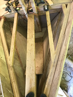
The chain locker is going in the bow in this section.  I will need to install floors over the longitudinal and glass all of it in with an above the waterline drain.  

That forward section is where the chain locker  will be located.  Fortunately, it is all above the waterline.

So, I will need to line the framing in that bow section with plywood and make a suitable floor for the chain locker. I also have to build in two bollards that bolt to the keel and go up through the decking to bolt to the bowsprit.  I'll have to block those in and create the locker around them.  It's an awkward space to work but I think I have a good plan.
I've laminate white oak for the bollards or vertical posts.  This is a rough-out one for the starboard side.

I only used clamp and epoxy to laminate the bollards.  I did not what any fasteners exposed.  The bollard will be bolted to the keel and the bowsprit with 3/4" stainless bolts.

Roughed to size and ready for shaping. There will be a narrowed section or waste above the deck to receive lines for towing, mooring and docking or whatever.

 There is no room at the stem to drill the 3/4" holes for the threaded rod that secures both bollards in place.  I'm going to have to drill right through the hull on one side and then patch that hole.  No way around it.


May 22.


Just checking the fitting of the bollards. I'll need to make a spacer at the bottom since the stem is 3 inches wide and the strong back at the bow is 6 inches wide. I also need to cut them to size and start shaping them.

You can see the spacers at the far end.  Since this area will eventually become the chain locker, I'll need to box in between the bollards.  I have also cut the bollards to equal length and rounded the ends and the inner corner that will eventually be glassed for the chain locker. 

The boxing cut out and placed for fit. You can see the outside edges have been rounded.


Shaped and ready for fitting. 

Looks like they fit pretty well.  The boxing in from is a little tight and I will do the final fitting when the bollards are bolted in and tightened.  I have also made and installed the back wall of the chain locker as you can see in this photo.  

I need to finish putting dead wood in where the plywood floors of the chain locker will attach.  

Wednesday, March 23, 2022

March 2022

 March 23,

Well, I had to have shoulder surgery.  A big repair to the right rotator cuff.  I've been completely out of action for two months.  I think it might be time to get back to working on the boat this weekend.  I look forward to posting some progress.

Tuesday, January 4, 2022

January 2022

 Jan 4,

Happy new year everyone!  

I've continued to install decking and the sides of the deckhouse.  The deckhouse sides are being permanently installed with epoxy and stainless steel screws.  The decking is being temporarily installed with drywall screws.  I want to be able to remove sections for access until the interior is finished but its also very nice to have a deck to walk on.  The bow section in particular will need to be taken back up when I build the anchor chain locker.  This should be water tight with drain holes.  I plan on being able to wash the chain down while it is in its locker to remove mud and salt.

I am installing the deckhouse sides first so that the deck between the gunwales  and deckhouse can be cut out of half a sheet of plywood.  I've clamped the plywood in place while I measure for the screw holes.  A screw is placed every 3 inches (7.5 mm) staggered up and down by 1.75 inches along the top and the same along the bottom.  

The deck is beveled to match the deckhouse sides and the bulwark.  

I want the deck plywood to break over the reinforced bulkheads.  I need a short deck piece here to keep the one before and after under 8 feet long.

A finished side... at least to just aft of the deckhouse.  The deck house side is glued and screwed while the deck is just temporarily fastened by a few drywall screws.


Another view of the finished side. I've screwed a temporary piece of plywood over where the two pieces of plywood are butt glued.  This is to make sure that they stay perfectly aligned while the epoxy hardens.  I use wax paper as a release so that the epoxy does not glue the temporary board to the boat.  Eventually there will be some sort of backing of the butt joint but I have not yet decided on what it will look like. Maybe something decorative. 


Wednesday, December 8, 2021

December 2021

Dec 8,

November was a slow month for the boat for time and financial reasons.  I've switched tacks a bit and started fitting the deck.  I am only fitting pieces at this time since I'll need to take some of it back up for access.

Fitting the port bow deck in two pieces.

This is the starboard bow deck piece showing the bevel cut for the deck.  I set the skill saw to the shallowest angle and make the cut.  I then use the "T" bevel to measure the angle every 12".  I can then mark the difference in the cut angle and measured angle on the plywood and use a hand plane to steepen the bevel so it fits.  It usually takes a bit of iteration to make it fit tight.

It is slow going.  Measure, cut, fit, remeasure, cut fit...