May 4,
Worked on the tanks again this weekend.
 |
| I am welding in the side of the black water tank that will fit in the curved bilge. I start by welding the inside. This side piece is critical because it will fix the curvature and define the one side that is square. I did not properly model the tank here and stepped back to produce a full three dimensional model. |
 |
| Shown here is the full three dimensional model. Note that the part that lays on the table is square while the rest is not. This is correct. When I welded the outside, enough heat is generated that the plastic relaxes into the correct angle. |
 |
| Heating the bottom of tank 2. I'm using the 3 dimensional jig (model or mold) of the tank here and the results were perfect. When I took off the clamps, the HDPE plastic did not spring back and laid comfortably on the mold (except for the very ends which easily clamp down). |
May 7,
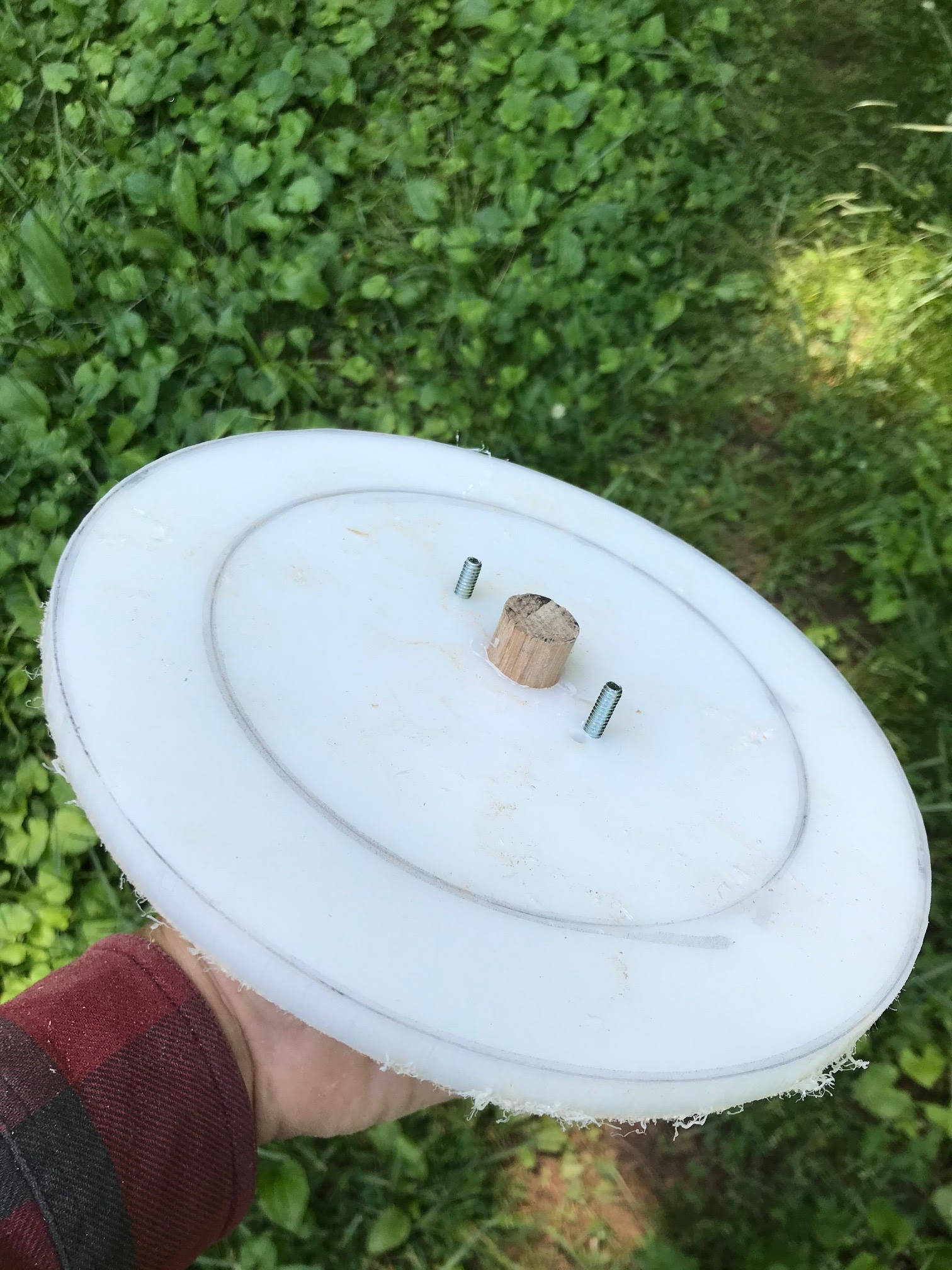
I took a lunch break and worked out how to make the inspection ports for the tanks. Basically I've cut out a 14.5 inch circular disk from the HDPE for a port cover and made a doughnut of the same outside diameter for a backing plate. I'm going to thread the backing plate and tank skin to accept a bolt. This is just to keep the bolts in place during installation. I will use nuts on the bolts to actually hold the port in place.
 |
| This will be the ring for my backing plate. I've mounted it on a jig to put in a wood lathe were I will cut out the center to leave a ring. |
 |
| Just the back side of that backing plate jig. |
 |
| Attached to a lathe and cut with a nice finish. |
 |
| inspection port cover in the top of the figure with the backing ring at the bottom. |
 |
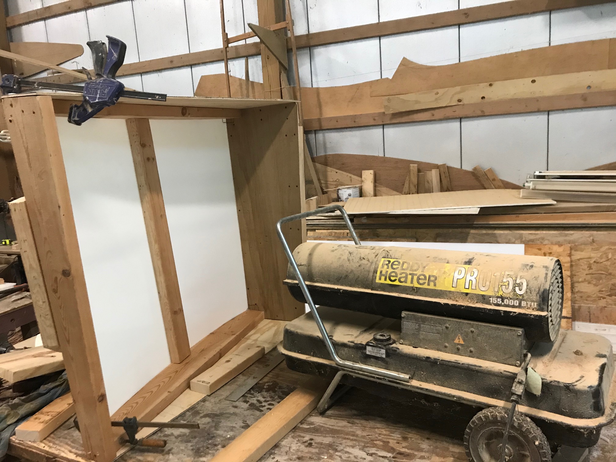
| Fitting the tanks. I placed the tanks in the bilge so I'd get the curvature to the sides correct. |
May 15,
 |
| Clamped up and ready to weld |
 |
| All four sides are in. |
 |
Measuring to build the first internal baffle.
|
 |
| Fitting the baffle. It needed a minor adjustment. Also note that there is now a lip around the edge that will eventually receive the top. |


No comments:
Post a Comment
Your feedback is very much appreciated.