Sunday, January 13, 2013

The Keel

Keel

The keel is the backbone of any boat or ship.  In traditional boat building it's the main structural element in which frames are attached.  It' also one of the first things built with everything else built around the keel.  The boat I'm building is not a traditional build boat but rather it's a hybrid.  In my case the keel is laid into the bulkhead after the hull already has its shape.  You've seen the keel temporarily installed in previous posts but now I'm ready to make it a permanent part of the boat especially since the temperature will finally be warm enough to actually use epoxy.  The temperature needs to stay above 60 degrees for at least 24 hours in order for epoxy to cure properly.  

Not so fast unfortunately.  I mentioned in an earlier post that the floor timbers continued to shrink after I had notched them for the keel (I had to take them all down and re-plane them before I installed them onto the bulkheads).  This forced me to raise (make the notches deeper) the keel around 3/16".  This should not pose and issues because a filler strake is used to bring the keel flush with the bottom of the hull after the hull planking is installed.  In a few instances I needed to lay in shims to bring the notches in the floor timbers down to the right level.  All of the notches in the floor timbers needed to be have at least minor adjustments.  

This figure shows thin laminations being glued into the bottom of the notches in order to maintain fairness of the keel. Three of the large floor timbers needed these laminations.  All required minor adjustments.
All the floor timbers back in place and ready for the keel.

Before I get to the keel, I used my shim making skills to fix a few other issues.  One of the longitudinal battens that terminated into the step was slightly recessed.  This was only apparent when I started to fare the bow by using thin battens bent onto the longitudinals.  I laminated a thin layer onto the batten and later I'll sand it down to shape.

Laminated a thin shim onto this longitudinal batten.  A short 1" X 2" board is used to apply even pressure to the shim to ensure that it is evenly bonded.  Wax paper is used to ensure that the clamping board can be removed after the repair is finished.

I decided to fix another issue while the temperature is nice.  A small 14 inch section of the third layer of the shear clamp became delaminated.  It's part of the shear clamp that was significantly shaped at the bow.  I clamped a piece of wood below the shear clamp where the repair was to be made so that the epoxy would not leak out of the bottom of the repair.  The separation in the shear clamp was filled with epoxy.  I then clamped the shear clamp tightly to ensure that the epoxy would be squeezed evenly throughout the delaminated section.  This is when I was reminded of what a liability cheap tools really are.  I figured 'C' clamps from Harbor Freight would work well enough.  I'd already bent a few but I had not broken one until now.  It's frustrating when your performing a critical task and your tools fail you.  The problem is that I need a very large number of 'C' clamps for this project and I figured I could get cheap ones.  There simple in function and made out of steal.  Actually, now I know they're cheap cast iron.  For the most part they have served their propose though.  I would recommend having a large number of cheap 'C' clamps for light clamping and a few good ones in critical situations.

Cheap 'C' clamps might not be worth the price.  I actually broke this 'C' clamp with hand pressure only.
The delamination of the shear clamp being fixed.  It looks complicated but it worked perfectly.
 Back to the repair. The repair looks awfully convoluted in the figure above but I was very pleased with the results.

After letting the epoxy set up overnight, I'm almost ready to install the first section of the keel.  A little sanding of repairs and I dry laid the first piece in place starting at the stern.  Drilled for the #10 2" silicon bronze screws and mixed up some epoxy.  I'll need a thickening agent for the epoxy so it will better fill small gaps.  The West epoxy, in its natural state, is very viscous and will run off a surface thats not flat.  There are various additives such as silica and micro spheres that thicken the epoxy and make it a better bonding agent.  I have just enough to make one batch of epoxy.  It turns out that I'm almost out of screws as well.  100 of these screws are $60 and the filler is around $30 but I'll have to order both from Jamestown Distributers.  I did, however, get that first piece (16 ft) installed.

Sunday, January 6, 2013

Buenas Notches

Many many notches later I finally finished the notches up to where the floor timbers start and then I ran out of wood for the longitudinal battens.  I would have  to save up some money which was getting a bit more difficult now that I have a new room mate (whom I married on October 7, 2012).  Nevertheless, I was able find enough money to get 500 board feet of lumber from Davie Ashley Sawmill in Elora, Tn. 

Stopping in Elora Tennessee for a quick drink after buying another load of white oak at Davie Ashley Sawmill.  This 16' trailer has paid for itself over and over again.  To the guy who literally took the next to the last corn dog out from under us at this convenience store (not pictured), you might want to avoid my wife for a while.  We actually ordered two corn dogs from one person behind the counter to have the guy behind us (yes he heard) order one from someone else who was quicker to the draw.  What is this world coming to when corn dogs and respect are in short supply.
I have at least one batten installed in all the notches up to the floor timbers.   You can see all the new battens that I made from the new load of wood waiting on the table in the foreground.
With this new load of wood I've changed the method of how I make the longitudinal battens.  Before I cut the wood to be as straight as possible and glued the battens together to be as straight as possible.  Now I'm ripping the lumber and following the natural curve of the wood.  The finished battens are then sorted by shape (straight, slight curve, radical curve, etc.)  I then select battens to fit the actual curves on the boat.  This has resulted in less waste and a much easier time fitting the battens into place at the cost of a little more time sorting and selecting the pieces.  I also gain increased strength since now the grain always carries true the entire length of the batten.  Before, I glued as manny battens as I could together.  Now, I can only glue up a few at a time and I've got to label and keep track of them.  I think its worth it though. There is less fighting to install them and I'm sure less internal stress in the final assembly.

The longitudinal battens finished up to the floor boards.  I've even faired the bulkhead to the hull contour in this photo.  Notice how the longitudinals flow smoothly into the stem.  This is no accident.
Back to the notches.  I've put together a series of photos that explains this grueling process.
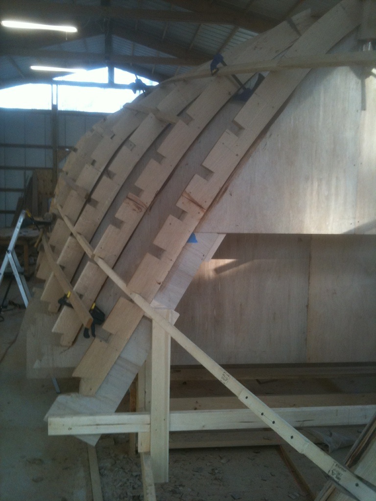
After measuring for the approximate placement of the battens (they should be as evenly spaced as possible), a long batten is clamped in place.  There is a trade-off between the best placement of the batten and the natural tendency for how the wood bends.  This was more of an issue during the more radical transitions between the barrel shape of the mid-hull region and the bow.  The gentle curves near the keel seem to follow a natural bend for the wood which means I laid the hull out in a smart fashion or more likely I got lucky.
Clamping the batten in place on top of the bulkhead frame.  This bulkhead also has a 3" floor timber bonded to it.

It's important that the batten is clamped so that it lies flat against the bulkhead.  Of course it can only lie flat on one edge of the bulkhead because the edge is square and the batten does not fall normal to the bulkhead.  I had to be careful not to over clamp the battens because I need to measure the angle between the batten and bulkhead.


I use a square to project where the notch sides should be drawn.   Even this is not straight forward because the square will not lay flat against the frame and sit flush on the batten at the same time.

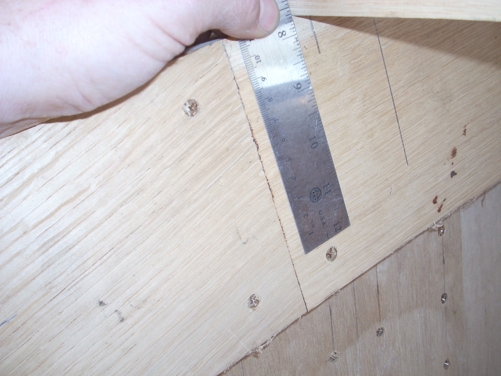
With the batten sitting naturally on top of the frame I measure the distance between the lowest part of the frame and the bottom of the batten.  This measurement plus two inches is what I will use for the depth of the notch from the bottom of the batten on both sides of the bulkhead.  Since the batten is at an angle to the bulkhead the final depth of the notch will actually be a little more (note the angle the rule makes to the batten and that the width measured at this angle is larger than the one inch thickness of the batten).  But this will get me close and I'll take the final measurements after I fit an actual batten into the notches.  


Marking the depth of the notch.

Notch drawn on the frame.

I've moved the clamp to the other side to mark this side.  The clamps often get in the way of marking the notches.

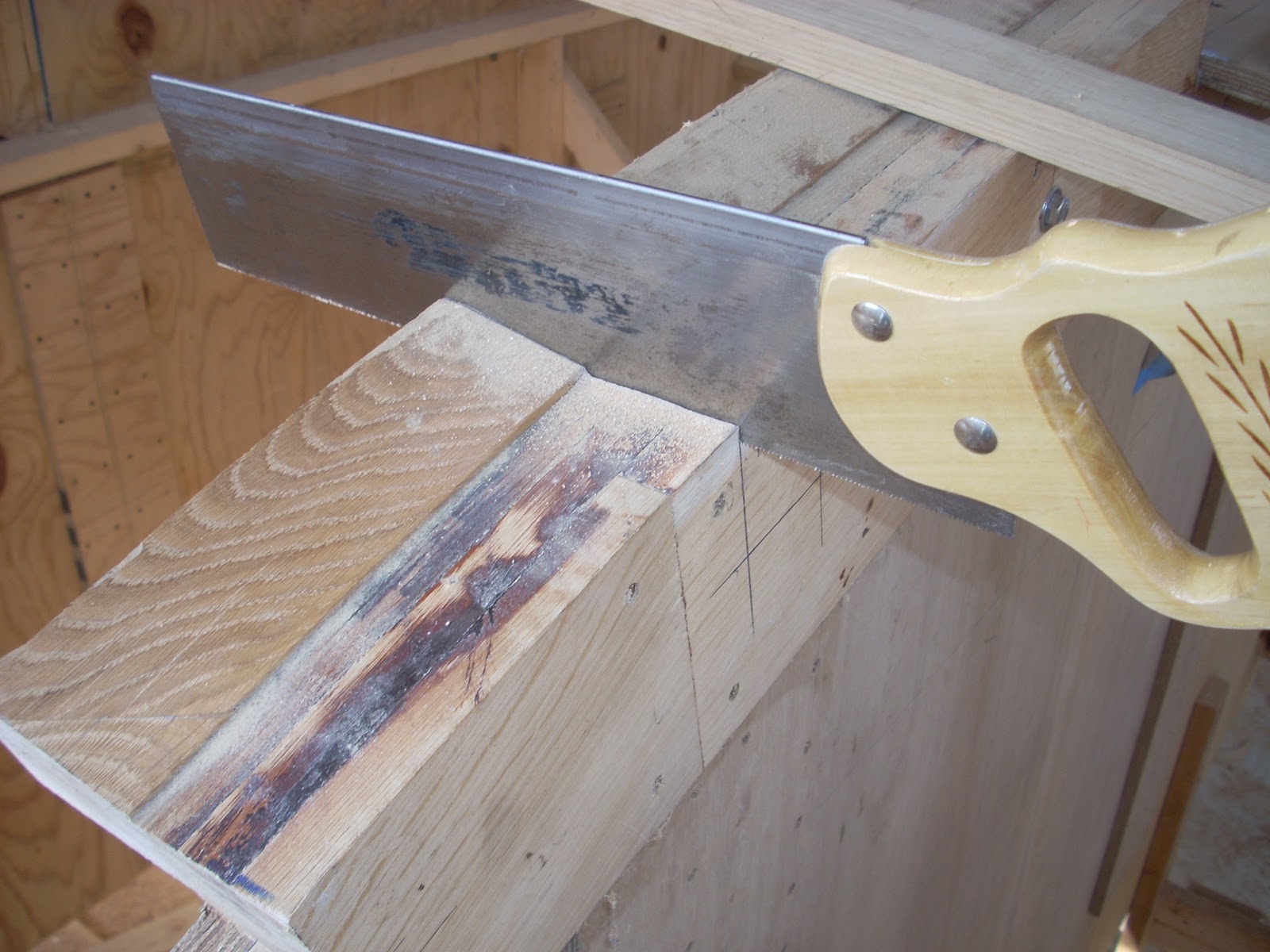
I start the cut for the sides of the notch with a hand saw.  I then use a Sawzall to cut most of the remaining side of the the notch.  I then finish with the hand saw.  I originally used the hand saw exclusively but I kept hitting screws hidden in the frames and after ruining 4 or 5 saws I switched to the Sawzall.  Ironically, the Sawzall is not really much faster than a sharp hand saw but the 4" floor timbers and frame combination is way too much for these short mitre saws and there is just no room for a long saw and once you hit a screw your done with that saw. 

The net step is to slice up the notches with a skill saw.  The skill saw is set to about 1 3/4" depth and I make 1/4" - 1/2" slices out of the notches.

A closeup of the slicing.

Some rough chisel work and the bulk of the material is cleared from the notches.

Notch cleared of the bulk of the material.

Using a hand saw, I make of cut in the center of the notch down to my depth lines on both sides of the frame.  I then can use a chisel and finish the notch.  Once a run of notches is cleaned out with the chisel I lay a temporary batten in place.  I note the places where it's too high and where the notch has the wrong angle.  Remember, I purposely designed the notches to be too high.  Now is where I measure the correct depth of the notches.  I also check to make sure the notches are not too tight.  A firm push or light hammer work should bring the batten flush to the bottom of the notch.  The most work is when the notches are too tight and I have to widen them.  This is painful chisel work especially where there are floor timbers.
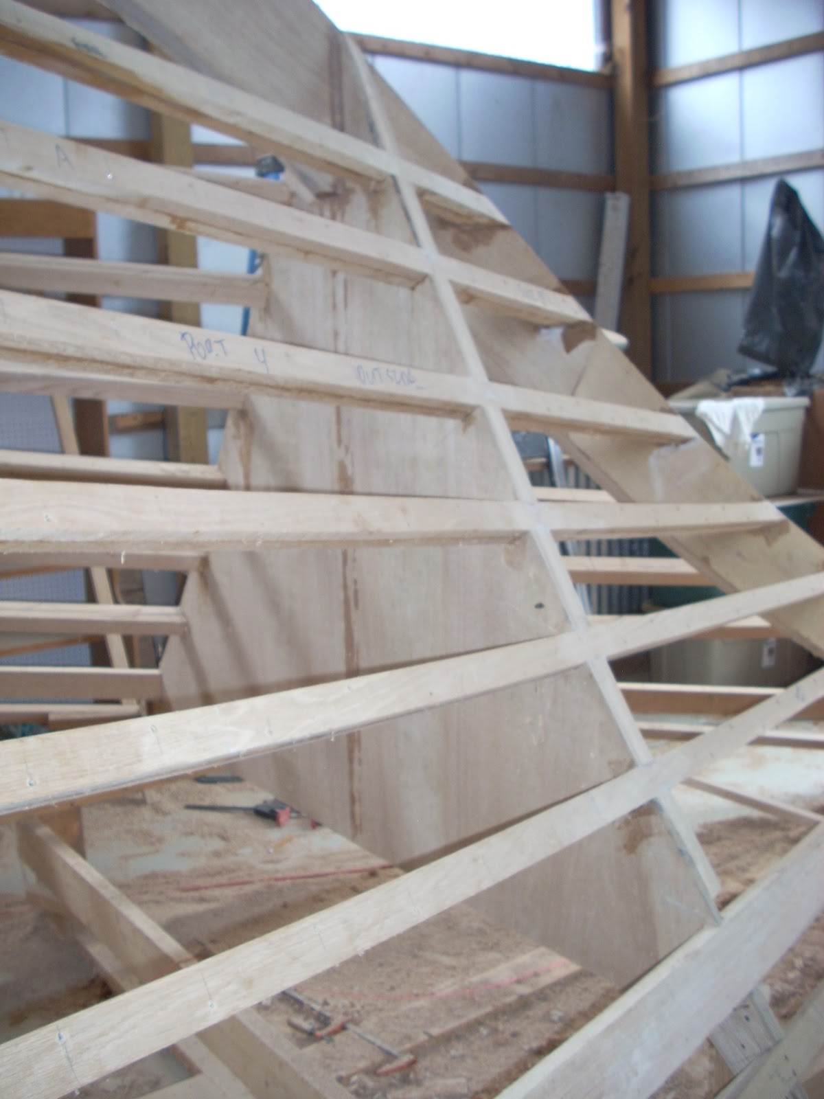
A finished run of notches.  I hope there is not an air vent 2 meters wide at the end of this trench because my defenses are built around a large scale attack.
13/02/02
This is my nephew Joshua learning how to make the notches.  It sure is nice to get help occasionally.  This is the last run of notches on the starboard side.  My goal is to have the hull ready for "planking" this spring.
13/02/10

Finally finished all the notches on the starboard side of the hull.  I have 3 more runs of notches on the port side to go.  The last two runs notch through all the floor timbers and these take about two days worth of work to get right.  It's also difficult to work on the bottom of the hull.  There are few places to keep tools.  Floor timbers are close together which makes working difficult.  Also it's like working on top of a jungle gym with nothing but sharp edges.  Well, I'll be glad when the last three runs are complete.  Tonight I'm exhausted.     
13/02/17

I'll add a picture soon.  I've started the final three runs of notches on the port side.  I didn't get too far this weekend because it was the weekend that I started the vegetable garden.  The garden is tilled, marked, fenced against rabbits, and the cabbage and lettuce has been planted.  All the other plants have been started inside.  Next weekend I'm going to try my hand at snow boarding so there won't be any progress for a few weeks.  Wish me luck.

13/04/02

Okay, so no snow boarding in 45 degree weather while it's raining.  Progress on the boat has be relatively slow but has not stopped.  Almost done with all the notches.

A close up of the work on the notches on the port side of the hull.

All the notches are roughed out and most are clean.  I have not laid in the longitudinal battens to check alignment or depth.  That is the next step.  

The Mundane Business of Building a Boat

Study, study, study

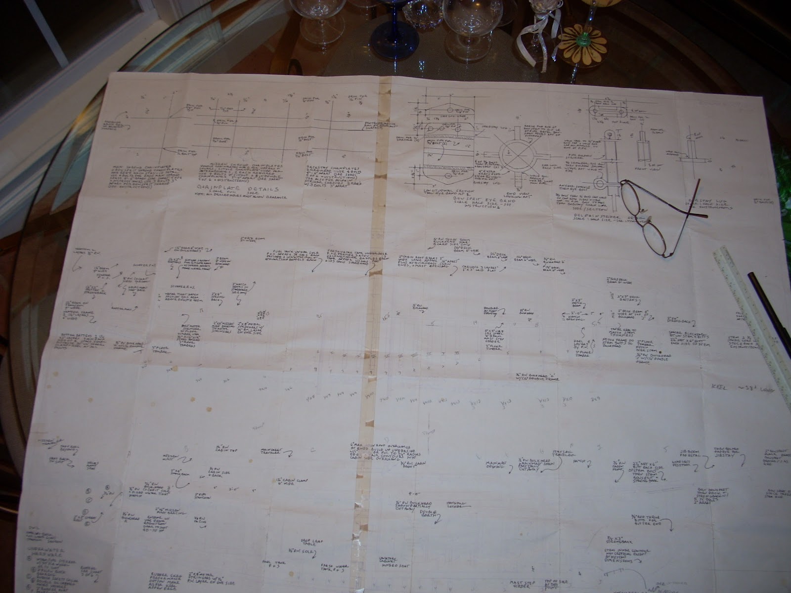
A good deal of my time is spent studying the plans and I've read through the instructions countless times.  You've really got to be familiar with the a great deal of the specifics before you even cut your first piece of wood.  So much of what you do will impact every stage of the construction it's imperative that you really understand what you are doing (See the section on building the transom).  The good news is that often a stage of construction will last a great deal of time and it's not necessary to have your nose in them all the time.  I spent a year on longitudinal battens and I'm still not done with them.  There was little need to consult the plans during this stage (well not often at least).  I did however read through the instructions a few times.  A few weeks ago I sat down to study the blue prints again because I'm about to lay in the keel permanently and I do not want to make any mistakes.  I do not know why, but in the two years I've been working with these plans they have faded and the paper has yellowed.  Parts are completely unreadable especially on sheet 4 of 6 (the most referenced page).  I realized that I should have had these sheets copied the day I got them and kept the originals sealed.  Now, blue prints are not used anymore.  Black line printers are the norm.  I asked a friend who's father owns a copy store specializing in plans to try to salvage what I have.  He was not able to bring out much of the faded lines but the black line will be much more durable and not subject to fading.  I still have one sheet that I'm having difficulty reading. 
Sheet 4 of 6.  These are actual blue prints so all the black that you see is where I've inked in what was faded.  There is still some missing information in the upper right that I can not recreate.  Luckily its just the dolphin striker and mounts that are difficult to read and I will not need this information for awhile.  Reading glassed, architect rule and an ink pen are the tools used for this work.

 I asked Glen-L Marine to send me new copies but they want $275.00 for a replacement set even though I do not need the large pattern sheets.  A local copy shop typically charges $5.50 a sheet not that I expected Glen-L to be that cheap.  I've asked Glen-L Marine to price me copies per sheet but I expect they won't do it [Actually after a bit of discussion they did much better than that and sent me the sheet I needed for free.  Go Glen-L Marine].  I realize that $275 is a measly amount of money compared to what the boat will actually cost but I put it in terms of what I could buy with that money such as 5 gallons of West epoxy.  Besides I'm still recovering from my wedding and honeymoon.  My temporary solution is to go over the plans with an ink pen filling in what I can.  I was amazed at what I was able to bring back but I'm still missing enough that I'll have to buy replacement plans.  The lesson is: make copies of your plans before you start.  Ironically, I made multiple copies of the instructions when I bought the plans because they were on old yellowed paper and they were fragile.  I wish I had thought to make copies of the plans.

I will say that I was able to get a good revue of the plans while retracing text and lines.  I actually did this on several sheets but none to the extent of sheet 4 of 6.  In reviewing the plans I realized that there is a floor timber on bulkhead 'J' that I had not fabricated yet.  It's only a 2" floor board and not very large but, hey, it is important.  The forward floor board supports the Vee berth as well as strengthens the joint where the stem, bitts and bulkhead come together.  I will make this piece out of two laminations of 5/4' stock that was too short to use as longitudinal battens.  Just goes to show you that you can look at the plans a hundred times and still see something you missed.  My advice is to look at them 200 times.

Monday, December 31, 2012

The Transom

The Transom

The transom is one of the most important pieces of a boat.  Traditionally it is the weakest part and generally targeted during naval battles (this goes back to the very first naval battles that used rams as the armament and continued through the development of the cannon, on the other hand it probably didn't matter where a modern torpedo hit you).  A failure in the transom has caused many a boat to go down.  the transom keeps the boat true.  The inherent sharp transition at the keel at the lack of timbers created the weakness.  The canoe removed this weakness by making the boat have essentially two bows front and back.  This design was utilized in large vessels as well as the common river variety that we are familiar.  In fact, you see many modern sailboats with this double ended design today.  Modern boat building techniques have largely reduced the liability of the transom to negligible levels. Nevertheless, I wanted to take particular care in constructing this part of the boat.  I'm not actually sure that I took extra care in its construction because I've been taking pretty damn extra care in the construction of the entire vessel but I will say that I was extra aware during this phase especially with all the difficulty this part caused me.  There are no patterns for the transom in the blue prints for this boat.  The plans call for taking the shape of the transom from the actual work after a few longitudinal battens are installed.  Really!  I'm looking at the stern of the boat and seeing the longitudinal battens forming nothing resembling the transom.  The port side of the boat in no way resembles the starboard side.  The reason is that no two pieces of wood will bend around the hull the same.  They all have slightly different internal tensions and, even though they might all start out straight, once you start bending them they will act different.  Here is where I deviate from the written instructions of the plans (this won't happen very often).  I decided to take the shape of the transom directly from the table of offsets.  Of course only the projection onto the flat sheet is provided by the offset tables but I'm pretty good at projections and undoing them.  Fifteen years working with sheet metal and creating finials and other decorative items out of flat stock well prepared me for this task.  The table of offsets show a beautiful wineglass shaped transom.  I spent some time transferring the lines to a pattern and voila' I had the transom shape I wanted.
Half the transom pattern shown upside down.  Never make a full sized pattern of a symmetrical piece.  You will never be able to get it perfectly symmetrical and these asymmetries will be magnified when you transfer the shape to the working piece.  Instead make half patterns and flip it to draw the second half.  This will ensure that the final piece is symmetric which is usually more important than getting the shape perfect. 

  I butt glued some plywood together and cut the first layer of the transom out (I had to include a little extra material around the edges because these edges would later be beveled to the shape of the hull).  The next and much more difficult part was placing the transom at the right angle and orientation at the rear of the boat.  For this, I built a jig (I'm a big fan of jigs).  Okay, so now the transom is on the jig and in position.  I have longitudinal battens rough cut to length on both sides.  I still have to install the frame on the transom (the transom frame will be a double lamination of 5/4" oak 6" wide).  I still do not know how to install the frames and notch them for the longitudinal battens without cutting into the transom itself (which according to the plans is a no no).  I decide to install a few longitudinal battens on the transom.  This is very rewarding because now I'm starting to see how the wine glass transom completes the beautiful lines of this boat.  After 3 or 4 longitudinal battens are installed on each side of the boat I decide it's time to tackle the frames.  
The installed transom with the frame transitioning from the inside of the battens to the edge of the transom.  The top of the picture shows the last of the frame pieces being glued in place with West System epoxy.  I used the West epoxy instead of the resorcinol glue because resorcinol glue has no filling capability.  This was a difficult glue-in procedure and I was unable to prevent small gaps in the work.  West System epoxy will remain at full strength with gaps (actually strong clamping pressure is discouraged with epoxy) while the resorcinol glue will loose most of its strength if not properly clamped.  I was able to make two notches in the frames before they were installed thus eliminating the need to notch the transom.  See the top two notches.  Actually I wasn't real happy with these notches which helped validate my decision to notch the first layer of the transom.  I felt with the my use of epoxy, which was not a design requirement, I would compensate for any weakness imparted onto the transom.
 Building the curved frames with complex notches cut in them using measurements only was a challenge.  I threw more than one piece of white oak into the kindling pile.  Worse, once I had a piece I liked it proved impossible to actually put into position.  There was no way to fit the finished piece onto the transom (I even tried a hammer).  This was a three dimensional puzzle that I could not crack.

My First attempt at making the frames around the longitudinal battens.  No matter how you twist or bang on this piece it will not fit due to the complex angles that the battens have as they meet the transom.  I made a pattern out of paper that fits perfectly but paper is two dimensional and bends easier than wood.  Time for plan 'B'.  I make this photo after I had finished the plan 'B' installation so you can see the finished solution behind this frame fragment.
Worse, the longitudinal battens were permanently installed so removing them was not an option.  Time for plan B (it's good to have a plan B).  I decided to move the frames to the inside of where the battens would be placed and then have them transition to their proper place once passed the installed battens.  I would later use dead wood between the battens to fill in the frames.  This would retain or even improve on the structural integrity of the transom while providing a way to attach the hull laminations.  For the battens not yet installed, I would notch the frames and the transom in contradiction to the plans.  I was pretty sure that the use of epoxy would offset any issues caused by cutting into the first layer of the transom (I must say that epoxy is not a miracle material and is no substitute for good craftsmanship.  I've seen epoxy cover a multitude of sins and just wonder at how those sins will surface later down the road.  Although it has saved my ass once or twice).  Luckily, only one layer of the transom was installed so the second layer would not be notched.  I have a thought to add a third layer to the transom so that there will be two un-notched layers on the transom.  To date, I have not decided.  I have figured out how to avoid this whole issue in the future.  The transom should have been made out of temporary material with the permanent frame attached.  The temporary transom and frame are then notched for the battens with the battens only being attached to the frames.  Once the battens are installed, the temporary transom is removed, the battens are cut flush to the frame and then both layers of the permanent transom is installed.  This sequence is easier than what I went through and conforms more closely to what the architect had in mind.  Lessons learned and passed on to you.

This image shows the frame transitioning form the inside to the outside of the battens.
After the dead wood is filled in between the battens.  A few more battens have been installed in this photo.  The hull shape is starting to look sweet.
A close up of the inside of the transom showing the frame transition.  This photo also shows the filler pieces in between the battens.  The work looks pretty messy because I wanted to make sure the pieces were well epoxied.  A bit of sanding will clean this right up.

Sunday, December 30, 2012

Floor Timbers

Floor Timbers

The floor timbers are large oak timbers that sit in the bottom of the hull.  Every bulkhead has one bolted to it plus there are several that float between bulkheads mid ship.  The ones that float are held in place by the longitudinal battens and are bolted to the keel.  They are called floor timbers because the sole is typically attached to them but they exist to hold the 12,400 pound ballast keel to the bottom of the boat. This ballast keel acts as a counterpoint to the force the wind places on the sails.  Extending four of five feet from the bottom of the boat the keel and the hull need to be rigid.  Long stainless steel bolts will pass through the ballast keel and into these floor timbers.  Where the ballast keel is located there is a floor timber every 12" or so.  The floor timbers that support the ballast keel are 4" thick with some roughly 14" wide.  The others that simply mount to the bulkheads are 3" thick and no more than 10" wide.  Their lengths vary from 6 to 12 feet.  Naturally I had to get these timbers custom cut which means green lumber.  Luckily, I ordered the lumber (from Davie Ashley Sawmill in Elora, Tn) in the fall which means that the trees had lost their sap when cut.  This speeds up the seasoning time for the lumber.  Nevertheless, I would have to wait a year before I could make the floor boards.  I didn't wait a year, I waited about six months.  I bought a moisture meter which was suppose to tell me when the wood was dry enough to work.  What it told me was when the outer half inch was dry enough to work.  Making a long story short, before bonding the timbers permanently to the bulkheads I took them back down and re-planed them flat so that they would mate flush to the bulkheads.  

Leaving Davie Ashley Sawmill in Elora Tennessee.  Thats a 16 foot trailer.  
Some of these timbers weighed several hundred pounds.  Remember at this point they are still green.  We had to get creative in unloading these.  We could not pick them up or slide them.  I used 1" iron pipe to roll them out Egyptian style.  Al's having a little fun while riding the wood off the trailer.  
After the timbers were mostly seasoned, I made patterns from the high side of the bulkheads.  This meant that I marked where the bulkhead top would be on what would be the widest side of the bulkhead.  Since all the bulkheads would eventually be tapered to follow the curve of the hull, there would always be one side a little longer than the other.  I needed to err on the side of wide when making these floor timbers.  I ended up with a pattern for each bulkhead.  When cutting out the floating floor timbers, I would use the largest bulkhead pattern in that area.  Few of the timbers were narrow enough to fit through the table top planer (12").  I planed the ones I could and precut the ones I thought would squeeze through after cutting to size.  The very wide ones I smoothed down with the hand power planer.  This was very time consuming.  I actually finished them with a hand planer to knock off the high spots.  They were all temporarily put in place and marked for the keel notches.  They were reinstalled and the keel notches were tweaked with hand saw and chisel.
Floor timbers with keel notches loosely where they will later be installed.  The ones grouped together are the floating floor timbers.
All the floating floor timbers needed to be shaped to the hull before the battens were installed.  There was no way I was going to be able to keep the hull fair while installing the battens any other way.  I came up with a clever scheme for making this happen.  I screwed 1" blocks of wood to a long batten with the same spacing as the bulkheads.  I then clamped the batten to the bottom of the bulkheads with the one inch blocks between the bulkheads and the batten.  If the floor timbers got in the way, I rough cut them down so that they were the correct size within that one inch margin.  The batten made a smooth spline that simulated the hull shape except one inch below the actual hull (or above the hull line depending on perspective).  I was then able to measure down one inch and mark both sides of the floor timber (actually I used a 1" marking block).   I repeated this procedure from one side of the floor timber to the other marking every few inches.  I then nailed brads where the marks were and bent a thin batten over the nails clamping one side to the closes longitudinal batten.  The thin batten created a fair line between the nails/marks.  This was the hull line for that side of the floor timber.  Once repeated on the other side of the floor timber, I used the hand held power planer to remove material down to the lines.
The batten with 1" block spacers that was used to shape the floor timbers.  Each 1" block would sit on top (bottom of the boat) of a bulkhead.
The floor timbers temporarily in place with one of four layers  of the keel laid in the notch.

Another view of the floor boards.  These have been shaped to the contour of the hull using the method described above.
First floor timber bolted and epoxied in place.  This small floor timber only merited two 6" X 3/8" stainless steel bolts.  

Second floor timber bolted and epoxied in place.  Most floor timber merit four 6" X 3/8" stainless steel bolts. 

Moving forward

Moving forward: The Last Bulkhead Under the Stem.

It was time to place the last bulkhead.  This one goes under the stem where the notch is located.  Forward of this bulkhead will later become the chain locker and storage.  To the rear of the bulkhead, will be the vee berth or forward cabin bed.  It's shaped like an inverted "V" to conform to the tapering hull line.  placing this bulkhead required building additional support to the jig because its the only bulkhead that floated above the jig.  Extra caution was used to assure that this bulkhead was straight and level.  Later I would find out that the placement for the deck clamp were mis-marked.  Another mistake that I would have to correct.  It required the addition of temporary support above (below in the current configuration.  When using word like above and below I will refer to the boat as it will be once turned right side up.)  This temporary support will be for the temporary bulwark clamp.  Note the word temporary everywhere.  Being temporary it did not matter that this support was not integral to the bulkhead.  Once this final bulkhead was placed I would need long (~55 feet) lengths of 5/4X2" oak to make the longitudinal battens that span the entire length of the boat.  These battens are what the actual hull planking will attach to.  They also create the length-wise shape of the hull.

Bulkheads showing notches for the longitudinals and a few longitudinals temporarily in place.  Thats my dog Hamlet in the background.  He's been my bud for a long time.
Oak in that length (55 feet) is not readily available.  Actually I did find a place that specializes in extremely long pieces of oak and other marine grade woods for traditional boat building projects but the prices reflect the rarity of the wood (I'll try to find that link and post it here later).  I knew that I would have to use shorter pieces of lumber and scarf them together.  A scarf joint is a typical technique for joining two pieces of wood together.  The simplest method would be to just end glue the two pieces of wood.  This creates a very weak joint in that there is only a small patch of glue and any bending of the joint maximizes the moment at the joint.  A scarf joint is created when the two boards end in long tapers.  These tapers are then matched and glued together.  This creates a large glued surface as well as having very little of the bending stress actually across the glue joint.
The two pieces of wood to be joined are labeled 'Battens.'  The length of the taper is typically 10-12 times the width of the wood.  I use clamping blocks to ensure even pressure along the glue joint.  Wax paper is use to prevent the glue from sticking to the clamping blocks.
Looking at the availability of lumber at mills that dealt with white oak I found it impossible to find 5/4" quarter sawn oak.  I decided to go with rift sawn lumber since I was cutting the boards down to 1.5".  At this width, dimensional stability would not be a problem and you can just think of it a quarter sawn boards 1.5" thick and 1" wide.  With this decision made, it was much easier locating lumber.  I found a guy who had two pallets of 5/4 rift sawn white oak.  The lengths were around 7 and 8 feet long.  Too short for what I needed but the price was cheap. Apparently no one wanted this lot and it had been taking up space at the lumber yard for a while.  The best part was the lumber yard was about an hour up the road in Tennessee so I could get it myself and not pay any shipping.  I purchase the lumber and started planing and cutting it to size.  I scarf joined a few pieces together and looked at the results.  I wasn't happy.  Once you cut off the checks and scarfed the ends, the pieces were way too short.  It would take too many to make up a longitudinal.  Actually I ended up using the ones I had made for the temporary bulwark clamps.  I ordered 16 foot 5/4" white oak from a lumber yard in Elora Tennessee.

A close up of glueing the scarf joints together.  The scarf joints are matched up and epoxy is applied.  A short clamping board is placed on both sides of the joint and pressure is applied using "C" clamps.  Wax paper is used between the clamping boards and the scarf joint to keep the epoxy from sticking to the clamping boards.

A wide shot of the scarfing process.  I used an old craftsman radial arm saw and a jig to produce the scarf.  you can see it in the upper right of the picture along with the floor timbers drying on the right.

I was much happier with these lengths and started making the first longitudinals for the boat.  With a few longitudinals I was able to clamp them bulkheads and mark out the notches.  Oh the notches.  The longitudinals need to be recessed into the bulkheads.  This requires cutting notches that are asymmetric, beveled, and a bitch to draw and cut.  There are 20 on each bulkhead.  I will spend an inordinate amount of time marking and cutting notches.  The best technique I found is to measure out the approximate placement of the longitudinals and then clamp one in place.  I then mark the actual location of the longitudinal from the clamped piece.  This is because wood does not always bend in a predicable manner and following the curve of the boat required a lot of wood bending.  Later I was very careful in the selection of the wood for longitudinals so that the natural bends in the wood would closely match those of the boat (There is a learning curve when attempting a project of this magnitude.  Things got easier as I gained experience).

This image shows the notching process.  The longitudinal (top of the figure) is clamped in place and the notches are drawn from its placement and orientation.  I used some cheap 1X2s to temporarily align the bulkheads as can be seen from the middle left to the bottom right corner of the figure.  this figure also shows the cut away bulkhead that will be under the forward "V" berth.  This is the only partial bulkhead.  The remainder of the bulkheads will have companion ways cut out after the hull is complete.

 I used a straight edge on the edge of the longitudinals to project the notch onto the bulkhead.  I then measured the depth (keeping it initially short of the necessary depth) of the cut on both sides of the bulkhead.  I initially used a hand saw to cut the sides of the notch.  I then used a skill saw to make several interior cuts and finally a chisel to clear out the notch.  After ruining a few hand saws by hitting hidden screws in the bulkhead I started using a sawzall.  I have a short throw sawzall thats great for precision work.  The blade has a short throw back and forth.  I used a very wide fine toothed blade.  I usually started the cut with the hand saw and finished it with the sawzall.  This was a good compromise between precision and buying a bunch of saws.  Besides, the wood saws you buy at a typical hardware store (Lowes or Home Depot) are junk.  I spend some time searching through them to pick out the best.  You'd be amazed at the variation in quality between 5 saws of the same brand on the same shelf.  A poorly made saw will cut crooked (or pull to one side in the middle of the cut) and there is nothing you can do about it.  A nice saw costs way too much ($100) to wreck on a screw.  I actually use the hand saw quite often during the construction of this boat.  Its much more precise and produces a smaller kerf than any powered saw.  Anyway, after I've chiseled a few notches clear down the side of the boat, I temporarily insert a longitudinal and check for straightness and depth.  I purposely left the depth short so I always had to clear a little more material at the bottom of the notch.  Often I would have to straighten it a bit or widen the notch a bit.  All in all, it was (is) a time consuming proposition.  

I'm king of the boat!  I've placed several longitudinal battens  and I'm notching out the bottom for the keel.  Did I mention that those notches are a real pain in the ass?
The longitudinal battens are temporarily laid into place once notches are cut the full length of the hull.  I use West System epoxy to bond the battens to the bulkheads as well as two silicon bronze screws per bulkhead.  The second lamination is bonded with West epoxy and screwed every six inches (staggered) with silicon bronze screws.  It is these screws that I later substituted for stainless steel.  These will be covered by the hull laminations and not subject to corrosion so I saw no reason in using the high dollar silicon bronze screws in this case.  A local supplier (Huntsville Fasteners) actually has the lowest prices on stainless screws I've ever seen or heard about.  They have smaller heads and no shank which is nice because I do not have to drill for the shank, only the countersunk head.  Did I mention how cheap these screws were.  The only downside is that later I had to shape the 3X3" shear clamp forward of the stem to make the hull fair.  I removed as many screws as possible but the screws in the oak were tight and several heads were stripped or broken making removal impossible.  The bronze screws are easily drilled out but the stainless screws are too hard.  The hand held power planer doesn't really notice the soft bronze screws but the stainless ones will notch the cutting blades in a heart beat.  I had to use a power grinder and grind down the screws below the wood and then use the power planer.  Nevertheless I went through a set of planer blades (one thus far).
Battens spanning the entire length of the hull.  The upper one (bottom of page) is the sheer clamp.  Its composed of three lamination of 5/4X3" white oak.  Only one is installed at this time.  In this picture you can just make out the first layer of the keel laid temporarily into the wide notch at the bottom  (top of the picture) of the keel.  No more squinting.  That's starting to look like a boat.
Attaching the first lamination of the 3" shear clamp into the stem.  The shear clamp needs to twist quite a bit to follow the contours of the hull.  In order to accomplish that I made this tool that allows me to twist the lumber and holds it in place.  This was also useful for some of the regular longitudinals as well.  

A close up of the longitudinal battens running into the stem.  Note that the battens have to be recessed behind the edge of the stem to so that the second lamination falls smoothly into the stem without leaving a gap or overhanging.


Some  of the second laminations of the battens going in on the port side.  In this photo all three laminations of the sheer clamp are installed on both sides.

Once I had a good start on the longitudinal battens, I decided to cut the plywood for the keel.  The keel runs the bottom of the boat and is make of 4 laminations of 3/4" plywood.  It widens considerably (16") midship and tapers fore and aft (6").  The keel lays in notches cut in the bottom of the bulkheads.  I temporarily laid the first layer of the keel in place (It made a nice walkway up there).  Floor boards, which are large timbers that the ballast keel is bolted to, will have to be fashioned and installed before I can permanently install the keel.  I was still unsure of the exact sequence I was going to use in the construction of the hull.  These keel pieces would lay around the shop for more than a year before I installed them (actually they are still not installed as of the writing of this page Dec 30, 2012).